Side-placed stage lamp optical system

A lighting and stage technology, applied in the field of side-mounted stage lighting systems, can solve the problems of affecting the light output effect, easy collision, inconvenient maintenance, etc., and achieve the effect of simplifying the lamp head structure, reducing space, and facilitating maintenance.

Active Publication Date: 2018-12-14
GUANGZHOU HAOYANG ELECTRONICS CO LTD
View PDF15 Cites 3 Cited by
  • Summary
  • Abstract
  • Description
  • Claims
  • Application Information

AI Technical Summary

Problems solved by technology

However, because the optical components are installed in four directions, some optical components are easy to touch the mounting plate or other optical components when cutting in or out of the light output direction, resulting in damage to the components in the lamp body bracket. ; Or the cavity of the lamp body bracket needs to be made large enough, resulting in an increase in the size of the entire stage lamp, which is not convenient for subsequent maintenance
Especially when installing the upper part of the component assembly, due to the influence of the mounting board, the components are easy to collide with each other or between the components and the mounting board, which will affect the light output effect, or even damage the components

Method used


Image

  • Side-placed stage lamp optical system
  • Side-placed stage lamp optical system
  • Side-placed stage lamp optical system

Examples


Embodiment

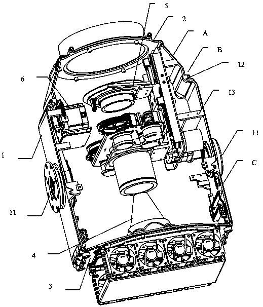
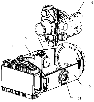
[0054] Such as figure 1 and figure 2 As shown, a side-mounted stage light optical system includes a lamp body bracket 1 arranged on the left and right, and a bracket top plate 2 is provided on the top of the lamp body bracket for installing a lens assembly; the lamp body bracket The bottom is provided with a bracket bottom plate 3 for installing a heat dissipation device; the lamp body bracket 1, the bracket top plate 2 and the bracket bottom plate 3 are jointly surrounded to form a lamp body frame, and a light source 4, an optical assembly 5 and The optical assembly 5 and the motor assembly 6 are installed on the inner wall of the lamp body bracket 1 to drive the motor assembly 6 of the lamp head structure of the stage lamp to rotate, and the effect assembly of the optical assembly 5 is rotatably arranged in the light emitting direction of the light source 4 .

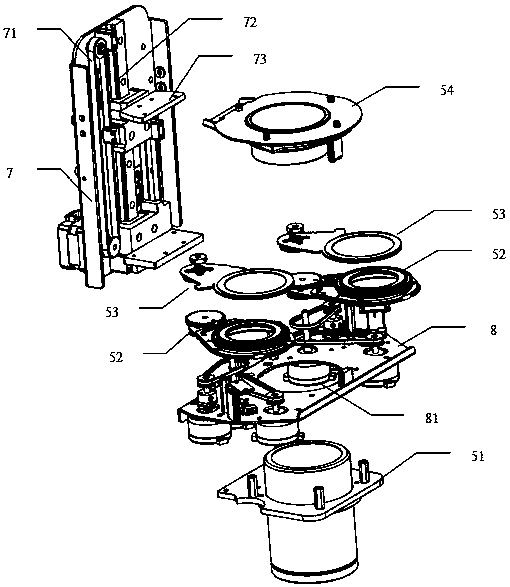
[0055] Such as image 3 As shown, the optical assembly 5 includes a focus lens assembly 51, a prism disk assembl...


PUM


Abstract

The invention discloses a side-placed stage lamp optical system. The side-placed stage lamp optical system comprises lamp body supports arranged left and right, a support top plate is arranged at thetop of the lamp body supports and used for installing a lens assembly. A support bottom plate is arranged at the bottom of the lamp body supports and used for installing a cooling device. The lamp body supports, the support top plate and the support bottom plate jointly surround to form a lamp body frame, the lamp body frame is internally provided with a light source and optical assemblies arranged in the principal optic axis direction of the light source, and the optical assemblies are installed on the inner walls of the lamp body supports. Compared with the prior art, the optical assembliesare arranged on the inner walls of the lamp body supports which are arranged left and right, the independent operation and non-interference of the optical assemblies and the stability and firmness ofthe lamp body supports can be effectively ensured, and the side-placed stage lamp optical system further has the beneficial effects of simple structure, more streamlined lamp body and convenient follow-up maintenance.

Description

technical field [0001] The present invention relates to the technical field of stage lights, more specifically, to a side-mounted stage light optical system. Background technique [0002] The lamp cap structure of the stage lamp in the prior art is generally divided into three parts: upper, middle and rear, and the sealing structure is formed by these three parts. Watertight seal. Due to the impact of the structure of the stage light lamp holder, the optical components in the prior art are installed on the mounting plate by setting the mounting plates in the front, rear, left and right directions of the lamp body bracket. Realize the stability of the installation of each optical component and its working performance. However, because the optical components are installed in four directions, some optical components are easy to touch the mounting plate or other optical components when cutting in or out of the light output direction, resulting in damage to the components in th...

Claims


Application Information

Patent Timeline
Patent Type & Authority Applications(China)
IPC IPC(8): F21S8/00F21V31/00F21V21/14F21V17/10F21W131/105F21W131/406
CPCF21S8/00F21V17/10F21V21/14F21V31/005F21W2131/406F21W2131/105
Inventor 蒋伟楷其他发明人请求不公开姓名
Owner GUANGZHOU HAOYANG ELECTRONICS CO LTD
Why Eureka
Try Eureka