
Method applied to equipment fault diagnosis and intelligent early warning of monitoring system

A technology for equipment failure and monitoring systems, which is applied in general control systems, test/monitoring control systems, and non-redundancy-based fault handling. Recovery of problems such as unclear distinction of logic to improve effectiveness and availability, reduce the probability of false alarms, and reduce storage space overhead

Active Publication Date: 2018-12-14
CASCO SIGNAL
View PDF7 Cites 8 Cited by
  • Summary
  • Abstract
  • Description
  • Claims
  • Application Information

AI Technical Summary

Problems solved by technology

[0002] Fault diagnosis and intelligent early warning are important functions of monitoring systems. At present, in monitoring systems, the distinction between equipment alarm logic and recovery logic is not clear, and the fault analysis methods are not uniform, which leads to chaotic execution of the system fault analysis process and increases the occurrence of false alarms. In addition, the fault analysis function of the traditional system is single, and the setting of fault generation and recovery conditions is simple, resulting in a large increase in the number of repeated alarms in the system, increasing storage space overhead and system CPU consumption, and increasing the workload of maintenance personnel; Failure analysis does not take into account the relationship between faulty devices, resulting in reduced referenceability of system failure analysis results and reduced availability of system functions

Method used


Image

  • Method applied to equipment fault diagnosis and intelligent early warning of monitoring system
  • Method applied to equipment fault diagnosis and intelligent early warning of monitoring system
  • Method applied to equipment fault diagnosis and intelligent early warning of monitoring system

Examples


Embodiment Construction

[0038] The technical solutions in the embodiments of the present invention will be clearly and completely described below, obviously, the described embodiments are part of the embodiments of the present invention, rather than all the embodiments. Based on the embodiments of the present invention, all other embodiments obtained by persons of ordinary skill in the art without making creative efforts shall fall within the protection scope of the present invention.

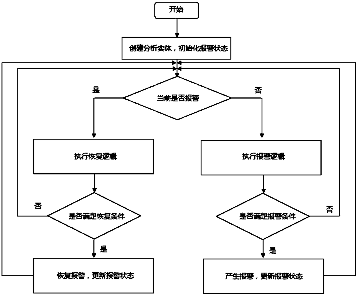
[0039] like figure 1 As shown, a method applied to monitoring system equipment fault diagnosis and intelligent early warning includes the following steps:

[0040] Step 1. Establish independent alarm analysis logic and recovery analysis logic based on the failure model of each alarm: based on the operating characteristics of the equipment, establish an alarm failure model, and define the equipment alarm logic and equipment alarm recovery logic;

[0041] Step 2. Control the execution of alarm logic and recovery logic ...


PUM


Abstract

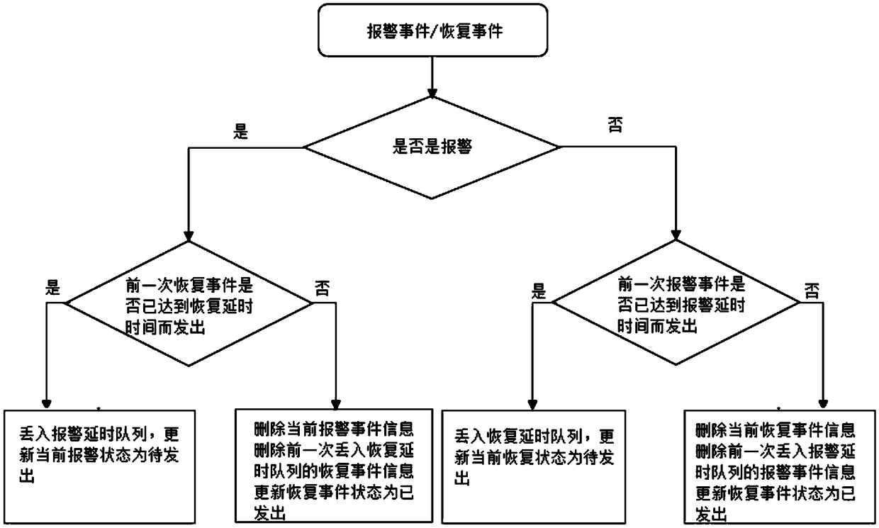
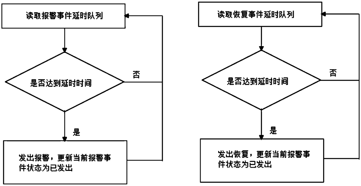
The invention relates to a method applied to equipment fault diagnosis and intelligent early warning of a monitoring system. The method comprises the following steps that 1, an independent alarm analysis logic and an independent restoration analysis logic are established on the basis of a fault model of each alarm; 2, the alarm logics and the restoration logics are controlled to be executed in a mutually exclusive mode; 3, delay processing is conducted on alarm events and restoration events; and 4, alarm events generated after delay processing are subjected to cascade relation establishment, alarm cascade groups are established according to the relation among different alarm events, whether or not the alarms in the same cascade group exist simultaneously in a certain time is automaticallyjudged by taking generation of the alarm events as a triggering condition, and association information among the alarm events is generated. Compared with the prior art, the method has the advantages of decreasing the false alarm generation probability and the invalid alarm number, reducing the storage space overhead, the system CPU consumption and the workload of maintenance personnel and the like.

Description

technical field [0001] The invention relates to the field of fault diagnosis and intelligent early warning, in particular to a method applied to fault diagnosis and intelligent early warning of monitoring system equipment. Background technique [0002] Fault diagnosis and intelligent early warning are important functions of monitoring systems. At present, in monitoring systems, the distinction between equipment alarm logic and recovery logic is not clear, and the fault analysis methods are not uniform, which leads to chaotic execution of the system fault analysis process and increases the occurrence of false alarms. probability; in addition, the traditional system has a single fault analysis function, and the setting of fault occurrence and recovery conditions is simple, resulting in a large increase in the number of repeated alarms in the system, increasing storage space overhead and system CPU consumption, and increasing the workload of maintenance personnel; Failure analy...

Claims


Application Information

Patent Timeline
IPC IPC(8): G05B23/02
CPCG05B23/0213G05B2219/24065G06F11/0772G06F11/079G06F11/0793G06F11/327G06F11/3075G08B23/00
Inventor 张吉亮胡恩华涂鹏飞朱存仁
Owner CASCO SIGNAL
Learn More