Hair curling and rotating mechanism for wig dyeing device

A technology of dyeing device and rotating mechanism, applied in wigs, applications, clothing, etc., can solve the problems of high price and cost, low yield, uneven hair dyeing, etc., and achieve the effect of simple structure

Inactive Publication Date: 2018-12-18
朱文统
View PDF0 Cites 0 Cited by
  • Summary
  • Abstract
  • Description
  • Claims
  • Application Information

AI Technical Summary

Problems solved by technology

Existing wigs are generally divided into human hair and artificial chemical fiber hair made of chemical materials. The latter is cheap, but it cannot be dyed and colored due to the material, which limits the choice of the wearer. The wig headgear is made after the hair of the person who arrives is processed. The price of the wig is relatively high, and the advantage is that it can be colored at will
The wig dyeing process is generally carried out in the wig dyeing device. The existing technology of this device is prone to uneven hair dyeing. For the manufacturer, the yield is low, which affects sales. For the wearer, it is not enough to wear. to the desired effect

Method used


Image

  • Hair curling and rotating mechanism for wig dyeing device
  • Hair curling and rotating mechanism for wig dyeing device
  • Hair curling and rotating mechanism for wig dyeing device

Examples


Embodiment Construction

[0023] In order to make the technical means, creative features, objectives and beneficial effects realized by the present invention easy to understand, the present invention will be further described below in conjunction with specific embodiments.

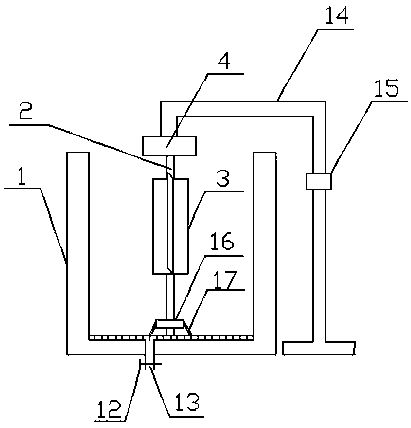
[0024] A curling rotating mechanism for a wig dyeing device, the specific embodiment of which is: a curling rotating mechanism for a wig dyeing device, comprising a rotating shaft 2, a hair roller and an outer sleeve 3 arranged in a dyeing barrel 1, and Including a mounting frame 14 and a controller 15, the bottom of the dyeing barrel 1 is provided with a dye discharge port 13, the dye discharge port 13 is provided with a switch valve 12, the upper end of the rotating shaft 2 is connected with a motor 4, the rotating shaft 2 The lower end is arranged on the bottom of the dyeing barrel 1 through a bearing assembly, the controller 15 is installed on the mounting frame 14, the outer sleeve 3 and the hair curler are detachably installed...


PUM


Abstract

The invention discloses a hair curling and rotating mechanism for a wig dyeing device. The hair curling and rotating mechanism comprises a rotating shaft arranged in a dyeing bucket, a hair curling cylinder and an outer sleeve; the lower end of the rotating shaft is arranged at the bottom of the dyeing bucket through a bearing assembly, the hair curling cylinder detachably sleeves the rotating shaft, and the outer sleeve sleeves the periphery of the hair curling cylinder; multiple openings are formed in the outer sleeve along the center axis of the outer sleeve, and a stirring plate is longitudinally and fixedly arranged at one sides of the openings; the hair curling cylinder comprises an outer cylinder body and an inner cylinder body, the inner cylinder body is embedded in the outer cylinder body, the bottom of the inner cylinder body is connected with the bottom of the outer cylinder body, and a cavity for a wig to wind is formed between the outer cylinder body and the inner cylinderbody; gripper assemblies for gripping hairlines are arranged on the outer wall of the inner cylinder body, a shell which turns outwards is connected to the edge of the upper end of the outer cylinderbody, and steam pipes are arranged between the shell and the outer cylinder body, and wind the periphery of the outer cylinder body. The hair curling and rotating mechanism is simple in structure; fuel heating is conducted through the steam pipes arranged on the hair curling cylinder, and the wig is uniformly dyed in the rotating process.

Description

technical field [0001] The invention belongs to the technical field of making wigs, and in particular relates to a curly hair rotating mechanism used in a wig dyeing device. Background technique [0002] With the improvement of people's living standards, people wear wigs in order to change their hairstyles in daily life. Wearing wigs can play a role in appearance modification. It is simple and convenient to change hairstyles, and it can also avoid damage to hair quality caused by perms, hair dyes and hair extensions. At the same time, it can save the cost of going to the barber shop to make hairstyles and dye hair. Existing wigs are generally divided into human hair and artificial chemical fiber hair made of chemical materials. The latter is cheap, but it cannot be dyed and colored due to the material, which limits the choice of the wearer. The wig headgear is made after processing the hair of the person who arrives. The price of the wig is relatively high, and the advantag...

Claims


Application Information

Patent Timeline
Patent Type & Authority Applications(China)
IPC IPC(8): A41G3/00
CPCA41G3/0075
Inventor 朱文统
Owner 朱文统
Why Eureka
Try Eureka