Hinged knee prosthesis

A knee joint prosthesis, hinged technology, applied in the direction of the knee joint, prosthesis, elbow joint, etc., can solve the problems of inability to achieve internal rotation and external rotation, and reduce the flexibility of the hinged knee joint prosthesis. To achieve the effect of improving the flexibility of use, facilitating the promotion and application, and safe and reliable use

Pending Publication Date: 2018-12-18
BEIJING CHUNLIZHENGDA MEDICAL INSTR
View PDF7 Cites 2 Cited by
  • Summary
  • Abstract
  • Description
  • Claims
  • Application Information

AI Technical Summary

Problems solved by technology

The femoral and tibial components are connected by a hinge assembly located in the intercondylar notch of the femoral condyle, allowing the hinged knee to achieve flexion and extension (collectively referred to as flexion and extension) with the help of the hinge assembly, but it cannot achieve internal rotation movement and external rotation (collectively referred to as external rotation), and thus reduce the flexibility of use of this hinged knee prosthesis

Method used


Image

  • Hinged knee prosthesis
  • Hinged knee prosthesis

Examples


Embodiment Construction

[0011] Specific embodiments of the present invention will be described in detail below in conjunction with the accompanying drawings.

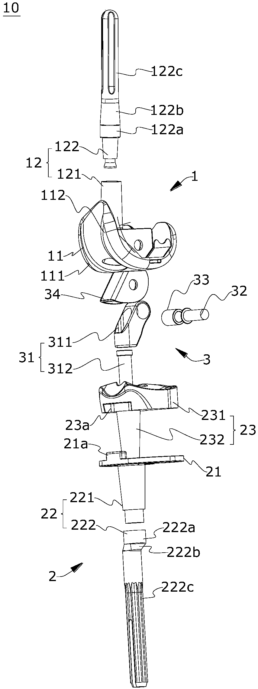
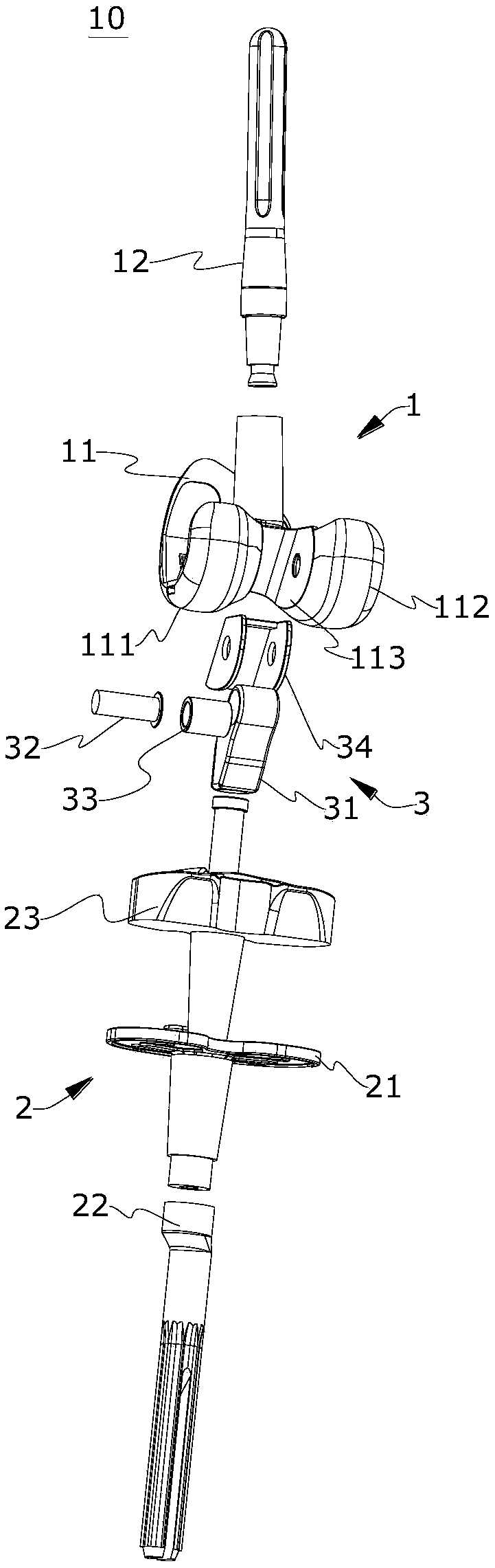
[0012] figure 1 shows an exploded schematic diagram of a hinged knee prosthesis according to an embodiment of the present invention; figure 2 The exploded schematic view of the hinged knee joint prosthesis according to the embodiment of the present invention is shown again in different viewing angles. Such as figure 1 and figure 2 As shown, the hinged knee prosthesis 10 mainly includes a femoral component 1 and a tibial component 2 that cooperate with each other, and a hinge component 3 for articulating the femoral component 1 and the tibial component 2 .

[0013] The femoral component 1 includes a femoral condyle 11 and a femoral pin 12 connected to each other. The femoral condyle 11 is mainly manufactured according to the anatomical shape and structure of the human femur, and the manufacturing material is preferably cobalt-chromium-mol...


PUM


Abstract

The invention relates to a hinged knee prosthesis comprising: a femoral assembly comprising a femoral condyle and a femoral medullary pin connected to the femoral condyle; a tibial assembly comprisinga tibial tray, a tibial medullary pin and a tibial pad, the tibial pad comprising a pad body and a hollow shaft, and the hollow shaft first passing through the tibial tray and then being coaxially inserted into the tibial medullary pin; and a hinge assembly comprising a hinged member disposed in a intercondylar notch of the femoral condyle and inserted into the hollow shaft and a hinged shaft passing through the femoral condyle and the hinged member. The tibial assembly is rotatable relative to the femoral assembly with the hinged shaft as the axis to allow the hinged knee prosthesis to perform flexion and extension. The tibial tray and the tibial medullary pin are rotatable relative to the tibial pad and the femoral assembly with the hollow shaft of the tibial pad as the axis to allow the hinged knee prosthesis to perform internal and external rotation. The hinged knee prosthesis of the invention can perform flexion and extension well as internal and external rotation, thereby effectively improving the flexibility of use thereof.

Description

technical field [0001] The invention belongs to the field of prosthesis implantation, in particular to a hinged knee joint prosthesis used in knee joint replacement surgery. Background technique [0002] Commonly used and effective knee replacement surgery mostly chooses hinged knee prosthesis. The existing hinged knee prosthesis includes a femoral component, a tibial component and a hinge component. The femoral and tibial components are connected by a hinge assembly located in the intercondylar notch of the femoral condyle, allowing the hinged knee to achieve flexion and extension (collectively referred to as flexion and extension) with the help of the hinge assembly, but it cannot achieve internal rotation movement and external rotation (collectively referred to as external rotation), and thus reduce the flexibility of use of the hinged knee prosthesis. Contents of the invention [0003] In view of all or part of the above problems, the purpose of the present invention...

Claims


Application Information

Patent Timeline
Patent Type & Authority Applications(China)
IPC IPC(8): A61F2/38
CPCA61F2/3859A61F2/389A61F2002/2892A61F2002/3011A61F2002/30329
Inventor 史春宝吕昌禹解凤宝李忠赵罡王上增闫新峰刘明远
Owner BEIJING CHUNLIZHENGDA MEDICAL INSTR
Why Eureka
Try Eureka