
Dust particle control device and system

A technology for dust particles and control devices, applied in chemical instruments and methods, cleaning methods and appliances, magnetic separation, etc. The effect of uniform force and improved safety performance

Pending Publication Date: 2018-12-18
东莞维科电池有限公司
View PDF0 Cites 0 Cited by
  • Summary
  • Abstract
  • Description
  • Claims
  • Application Information

AI Technical Summary

Problems solved by technology

[0004] The purpose of the present invention is to provide a dust particle control device to solve the technical problems in the prior art that the dust suction device, static electricity removal device and iron removal device are independently installed, resulting in complex structure of the winding machine and uneven force on the pole pieces
[0005] The purpose of the present invention is also to provide a dust particle control system, the dust particle control system includes the above-mentioned dust particle control device, which is used to solve the problems caused by the independent setting of the dust suction device, static electricity removal device and iron removal device in the prior art. The technical problems of the complex structure of the winding machine and the uneven stress of the pole piece

Method used


Image

  • Dust particle control device and system
  • Dust particle control device and system
  • Dust particle control device and system

Examples


Embodiment 1

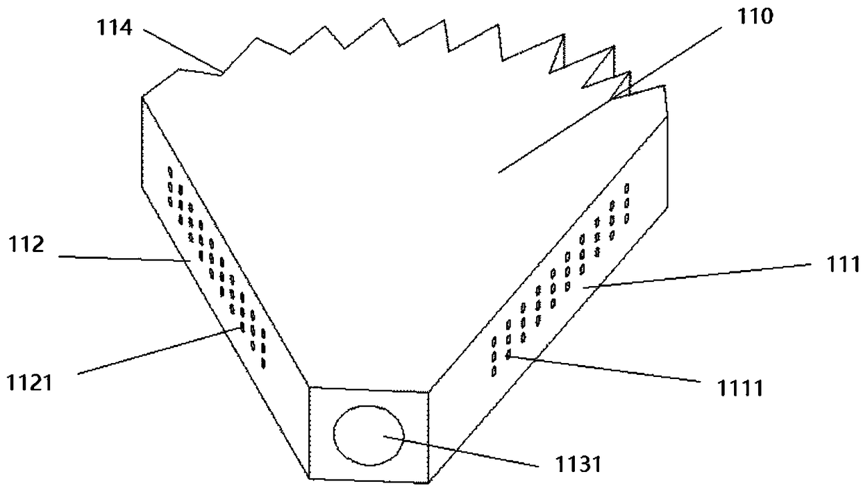
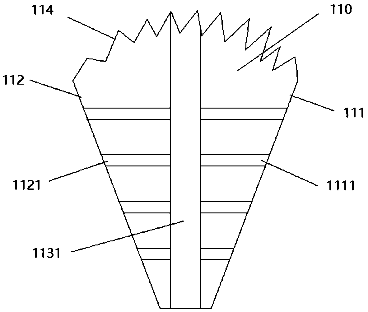
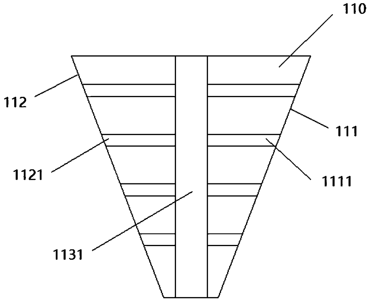
[0041] figure 1 Schematic diagram of the structure of the first structure of the dust particle control device provided by the embodiment of the present invention from a first perspective; figure 2 Schematic diagram of the second view of the first structure of the dust particle control device provided by the embodiment of the present invention; image 3 Schematic diagram of the second structure of the dust particle control device provided by the embodiment of the present invention; Figure 4 It is a schematic structural diagram of the third structure of the dust particle control device provided by the embodiment of the present invention.

[0042] Such as Figure 1 to Figure 4 As shown, a dust particle control device 100 is provided in this embodiment, and the dust particle control device 100 includes a dust removal body 110;

[0043] The dust removal body 110 includes an iron removal surface 111 and a static electricity removal surface 112 arranged at an angle; the intersec...

Embodiment 2

[0068] Figure 5 Schematic diagram of the structure of the dust particle control system provided by the embodiment of the present invention.

[0069] Such as Figure 5 As shown, the dust particle control system provided in this embodiment includes the dust particle control device 100 provided in the first embodiment, and the technical solution described in the first embodiment also belongs to this embodiment.

[0070] Specifically, as Figure 5 As shown, a dust particle control system is provided in this embodiment, the dust particle control system includes a winding machine 200, and the dust particle control device 100;

[0071] The winding machine 200 is provided with a positive pole piece fixing position 210, a negative pole piece fixing position 220, and two separator fixing positions 230; the positive pole piece fixing position 210, the negative pole piece fixing position 220, And the two isolation membrane fixing positions 230 are arranged symmetrically with respect t...


PUM


Abstract

The invention provides a dust particle control device and system, and relates to the technical field of dust removal. The dust particle control device comprises a dust removal body; the dust removal body comprises an iron removal face and a static removal face which are arranged to form an angle; the intersection ends of the iron removal face and the static removal face are connected through a connecting plane. A first dust collecting pipeline stretching into the dust removal body is arranged on the connecting plane, and is connected with the output end of an aspirator pump. A second dust collecting pipeline communicating with the first dust collecting pipeline is arranged on the iron removal face. The static removal face is used for removing static on an isolating film. The iron removal face is coated with magnetic matter which is used for adsorbing metal chips. The dust particle control system comprises a winding machine and the dust particle control device. The dust particle controldevice is fixed to the winding machine. According to the dust particle control device and system, the technical problems that due to the fact that in the prior art, a dust collecting device, a staticremoval device and an iron removal device are independently arranged, the winding machine is complex in structure, and pole piece stress is uneven are solved.

Description

technical field [0001] The invention relates to the technical field of dust removal, in particular to a dust particle control device and system. Background technique [0002] In the current production and winding process of the dust particle control system, due to the swarf produced by the tab welding, the electrostatic effect of the isolation film, and the iron filings on the pole piece, we need to add a dust collection device and a static electricity removal device to the equipment. And the iron removal device, which makes the device on the winding equipment too cumbersome; and the current dust removal device sucks dust from the end face of the pole piece and the isolation film, which will cause uneven force on both ends of the isolation film and thus It is easy to cause the internal short circuit due to the folding of the separator during winding. [0003] Based on this, the present invention provides a dust particle control device and system to solve the above technical...

Claims


Application Information

Patent Timeline
IPC IPC(8): B08B5/04B03C1/30H05F3/00
CPCH05F3/00B03C1/30B08B5/04Y02E60/10
Inventor 李惠昌朱坤庆计阳聂灿夏小勇
Owner 东莞维科电池有限公司
Learn More