Collecting and conveying pipeline segmented pipe cleaning system and method

A pigging and pipeline technology, which is applied in the field of segmented pigging systems for gathering and transportation pipelines, can solve the problems of low cost performance, stuck balls, and low frequency of use, and achieves the effects of long digestion time, simple structure and clear functions.

Active Publication Date: 2018-12-18
CHINA PETROLEUM ENG & CONSTR +1
View PDF10 Cites 7 Cited by
  • Summary
  • Abstract
  • Description
  • Claims
  • Application Information

AI Technical Summary

Problems solved by technology

The above methods have their own application characteristics and limitations: regular pigging can theoretically control the amount of liquid accumulation in the pipeline, but frequent pigging has problems such as high operation and maintenance costs and increased operational risks, and there are also problems in the calculation of the pigging cycle. Certain deviation; Although the expansion of the downstream slug catcher can theoretically solve the problem of extreme slug flow load, the project investment is extremely high, and the frequency of equipment use is relatively low, so the cost performance is not high; Bypass pigging is practical in practice There is a minimum flow rate requirement during the operation. In low-speed operation, problems such as ball jamming may occur, and the operation risk is greater than that of the ordinary pigging method; section-by-section pigging needs to set up intermediate pigging stations (with receiving and receiving ball barrels), and there are many equipments. High investment, high management requirements, and relatively low frequency of use

Method used


Image

  • Collecting and conveying pipeline segmented pipe cleaning system and method
  • Collecting and conveying pipeline segmented pipe cleaning system and method

Examples


Embodiment Construction

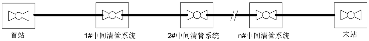
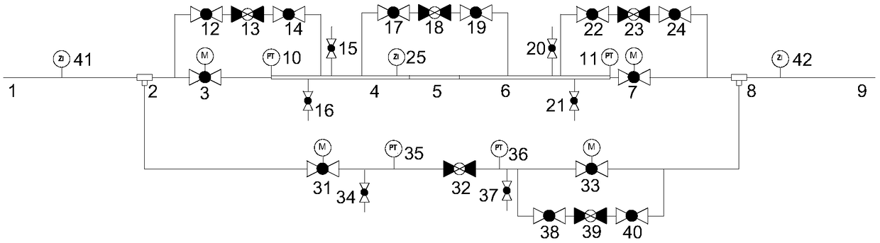
[0025] A segmented pigging system for gathering and transportation pipelines, such as figure 1 and figure 2 as shown,

[0026] The total system includes: the first station A, the intermediate pigging system 1#, the intermediate pigging system 2#, ..., the intermediate pigging system n# and the final station B; After the selection, it is used to reduce the one-time long-distance pigging slug load, the downstream pigging first, and then the upstream pigging.

[0027] Each intermediate pigging system is a separate subsystem, including: upstream incoming pipeline 1, upstream reducing bar tee 2, upstream main line ball valve 3, first-stage thick-walled pipe joint 4, second-stage thick-walled pipe joint 5, Third-stage ball joint 6, downstream main line ball valve 7, downstream reducing bar tee 8, downstream outbound pipeline 9, main line pressure transmitter 10 / 11, bypass ball valve 12 / 14 / 17 / 19 / 22 / 24. Bypass control valve 13 / 18 / 23, gas release replacement valve 15 / 20, liquid re...


PUM


Abstract

The invention discloses a collecting and conveying pipeline segmented pipe cleaning system and method. The collecting and conveying pipeline segmented pipe cleaning system comprises at least one intermediate pipe cleaning system arranged along a collecting and conveying trunk line, and the intermediate pipe cleaning system comprises a trunk pipe cleaner staying / transmitting system, a large bypasssystem, a pipe cleaner indicating system and a logic control system. Compared with the prior art, the segmented pipe cleaning system has the positive effects that on the basis of accumulated liquid and slug injection load process analysis, pipeline section plug flow digestion is carried out in a sectional pipe cleaning mode; and by means of inverse-sequence pipe cleaning, the volume of the pipeline after the downstream advance pipe cleaning is utilized to the largest extent, so that the upstream incoming liquid receiving is achieved, the plug flow load of the end point section is reduced, andextension of a large-scale section plug flow catcher is avoided. The pipe cleaning system is simple in structure; and compared with addition of a conventional cleaning station, according to the the collecting and conveying pipeline segmented pipe cleaning system, a pipe cleaner ball collecting barrel, a ball serving barrel and accessory facilities can be avoided, and the system has advantages in large-caliber and high-pressure pipeline engineering projects.

Description

technical field [0001] The invention relates to a segmental pigging system and method for a gathering and transportation pipeline. Background technique [0002] With the increasing requirements for the development of onshore gas fields, the characteristics of the main gathering and transportation pipelines tend to be long distances, large pipe diameters, and high pressures. Gathering and transportation pipelines in gas fields generally adopt the gas-liquid mixed transportation mode. With the undulating terrain, the problem of liquid accumulation in the pipeline is inevitable. Pipeline effusion is affected by many factors, mainly including pipeline transportation volume, medium gas-liquid ratio, and pipeline topography. Especially for mixed transportation pipelines in the early stage of production and the end of production, during low-volume production increase, low-volume pigging, or full-line intelligent detection, it may induce liquid accumulation in the pipeline to form ...

Claims


Application Information

Patent Timeline
Patent Type & Authority Applications(China)
IPC IPC(8): B08B9/057B08B13/00
CPCB08B9/057B08B13/00
Inventor 陈俊文汤晓勇谌贵宇杨帆郭艳林余洋王磊昝林峰陈静冯琦马艳琳汤智昀
Owner CHINA PETROLEUM ENG & CONSTR
Why Eureka
Try Eureka