Pipeline grinding equipment for building
A technology for construction and piping, which is applied in grinding/polishing equipment, metal processing equipment, and machine tools designed for grinding the rotating surface of workpieces, etc. Improve the quality of grinding, reduce manpower operation, and reduce the effect of work intensity
- Summary
- Abstract
- Description
- Claims
- Application Information
AI Technical Summary
Problems solved by technology
Method used
Image
Examples
specific Embodiment approach 1
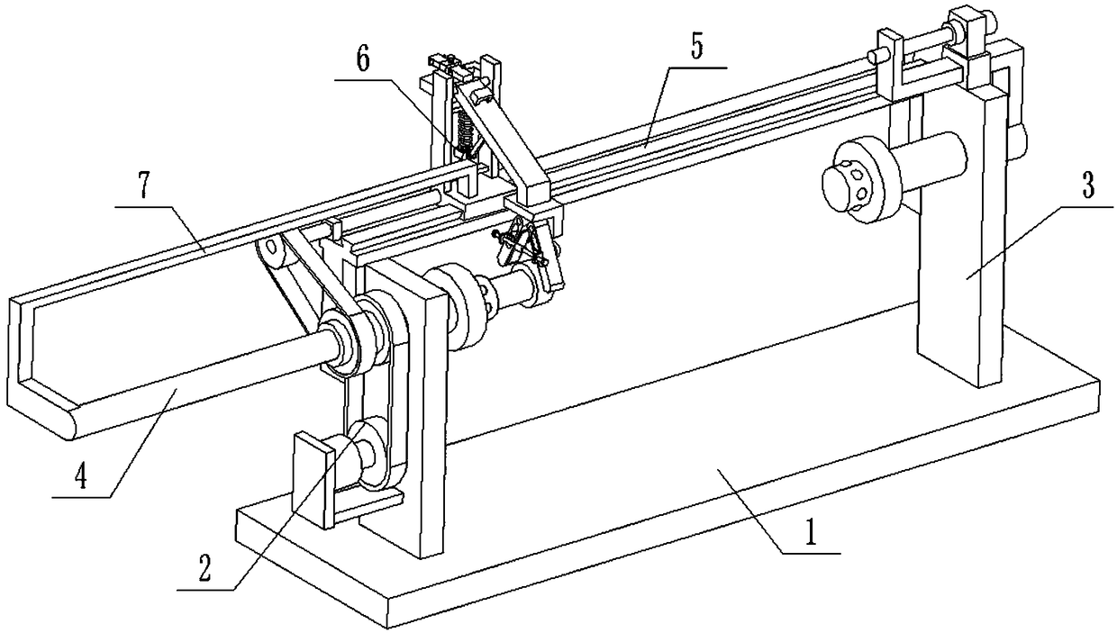
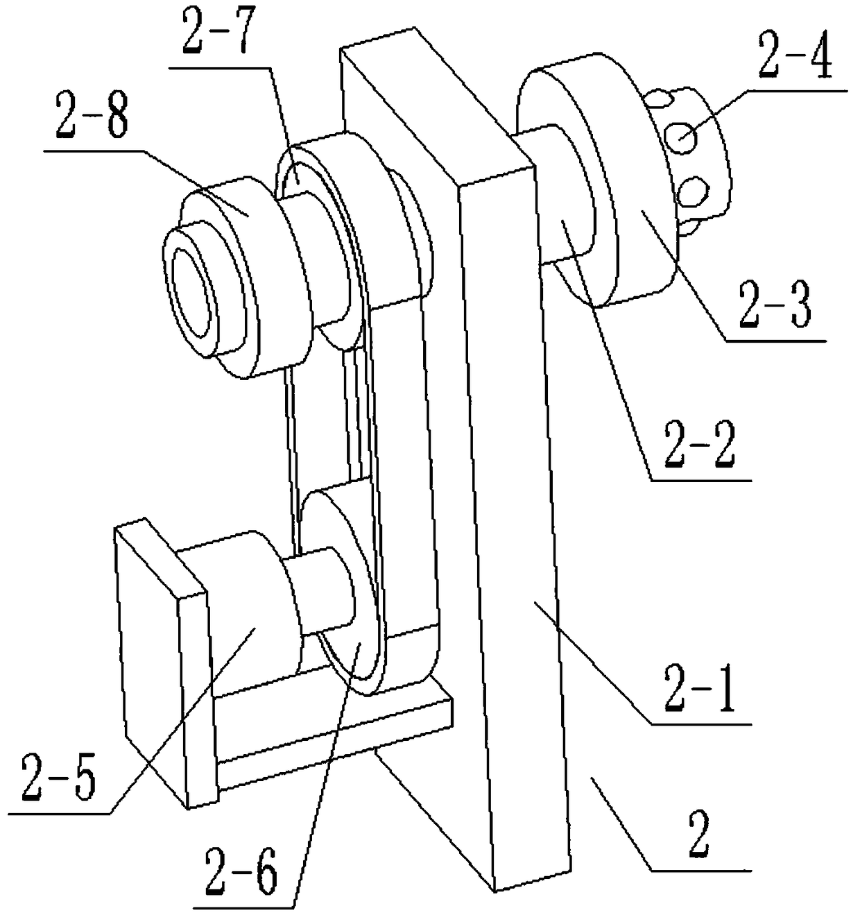
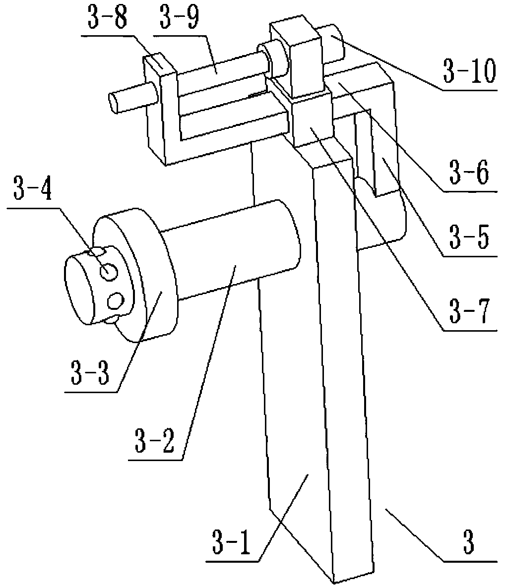
[0031] Combine below Figure 1-12Describe this embodiment, a pipe grinding equipment for building construction, including a bottom plate 1, a left pipe support 2, a right pipe support 3, an inner surface grinding part 4, a slide rail seat 5, an outer surface grinding part 6 and a connecting arm 7 , the left pipe support 2 includes a left support plate 2-1, a shaft sleeve 2-2, a left top seat 2-3, a rubber protrusion I2-4, a motor I2-5, a driving pulley 2-6, and a The driving pulley 2-7 and the driving pulley 2-8; the left support plate 2-1 is fixedly connected to one end of the base plate 1, and the middle end of the axle sleeve 2-2 is connected to the left support plate 2-1 through a bearing with a seat for rotation , the left top seat 2-3 and the driving pulley 2-8 are respectively fixedly connected to the two ends of the shaft sleeve 2-2, and a plurality of rubber protrusions I2-4 are evenly arranged on the shaft sleeve 2-2, and a plurality of rubber protrusions I 2-4 are ...
specific Embodiment approach 2
[0036] Combine below Figure 1-12 To illustrate this embodiment, the axes of the telescopic shaft 3-2, the sleeve 2-2, the smooth rod 4-1 and the grinding disc 4-2 are all coincident, so that the axes of the inner wall and the outer wall of the ground pipe do not deviate from each other.
specific Embodiment approach 3
[0037] Combine below Figure 1-12 To illustrate this embodiment, the outer surface grinding part 6 also includes a door-shaped seat 6-22, a sliding sleeve for inserting rod 6-23, an inserting rod 6-24, a blocking piece 6-25, a fastening screw 6-26 and Fixed sliding sleeve 6-27; The two ends of door font seat 6-22 are fixedly connected on two vertical frame plates 6-3 respectively, and insert rod sliding sleeve 6-23 is fixedly connected on the door font seat 6-22, The insertion rod 6-24 is slidingly connected in the insertion rod sliding sleeve 6-23, and the insertion rod sliding sleeve 6-23 is threadedly connected with a fastening screw 6-26, and the fastening screw 6-26 is pushed against the insertion rod 6-24 , the insertion rod 6-24 is fixedly connected with two baffles 6-25, and the two baffles 6-25 are respectively located at the two ends of the insertion rod sliding sleeve 6-23; the connecting plate 6-10 is fixedly connected with a fixed Sliding sleeve 6-27.
[0038] W...
PUM
 Abstract
Description
Claims
Application Information
 - R&D
- Intellectual Property
- Life Sciences
- Materials
- Tech Scout
- Unparalleled Data Quality
- Higher Quality Content
- 60% Fewer Hallucinations
Browse by: Latest US Patents, China's latest patents, Technical Efficacy Thesaurus, Application Domain, Technology Topic, Popular Technical Reports.
© 2025 PatSnap. All rights reserved.Legal|Privacy policy|Modern Slavery Act Transparency Statement|Sitemap|About US| Contact US: help@patsnap.com


