
Automatic polishing and chamfering equipment for both ends of building reinforcement materials

A technology for automatic polishing and building steel bars, which is applied in the direction of grinding/polishing equipment, metal processing equipment, surface polishing machine tools, etc. It can solve the problem that polishing and chamfering work cannot be carried out at the same time, which affects the construction efficiency of the construction site and costs a lot of human resources. and other issues, to reduce the consumption of human resources, improve processing and construction efficiency, and achieve the effect of construction efficiency

Active Publication Date: 2020-06-19
宇宸江苏建筑工程有限公司
View PDF10 Cites 0 Cited by
  • Summary
  • Abstract
  • Description
  • Claims
  • Application Information

AI Technical Summary

Problems solved by technology

[0002] In recent years, with the continuous development of the economic level, my country's real estate industry has developed very rapidly. On the construction site, a lot of building materials are needed for construction. Steel bars are a common building material in the construction site. In the process, it is often necessary to polish and chamfer both ends to meet the needs of actual production. The traditional polishing and chamfering work needs to be done manually. Such an operation method not only requires a lot of human resources, but also is inefficient. , and the traditional polishing and chamfering work cannot be carried out at the same time, which will affect the construction efficiency of the site

Method used

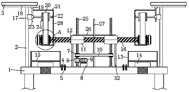
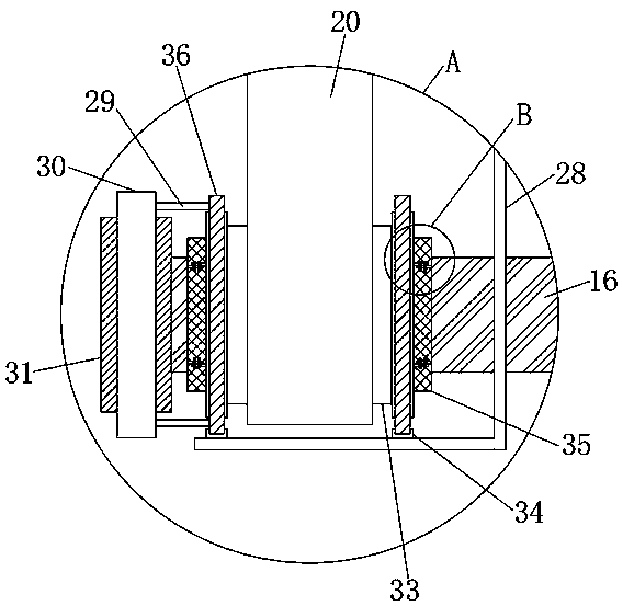
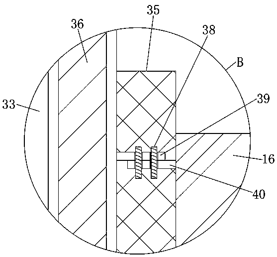

Image

  • Automatic polishing and chamfering equipment for both ends of building reinforcement materials
  • Automatic polishing and chamfering equipment for both ends of building reinforcement materials
  • Automatic polishing and chamfering equipment for both ends of building reinforcement materials

Examples


Embodiment Construction

[0027] The technical solutions in the embodiments of the present invention will be clearly and completely described below with reference to the accompanying drawings in the embodiments of the present invention. Obviously, the described embodiments are only a part of the embodiments of the present invention, but not all of the embodiments.

[0028] refer to Figure 1-6 , the automatic polishing and chamfering equipment at both ends of the building steel bar material, including a workbench 1, the upper end of the workbench 1 is provided with a clamping device, the clamping device is provided with a workpiece 16 to be processed, and the clamping device includes two support rods 32, two The upper ends of the support rods 32 are fixedly connected with the first clamping plates 11 , the workpiece 16 to be processed is placed on the upper ends of the two first clamping plates 11 , and the upper ends of the worktable 1 are rotatably connected with two first threaded rods 25 , wherein ...


PUM


Abstract

The invention discloses an automatic polishing and chamfering device for the two ends of a building reinforcing steel bar material. The device comprises a workbench, a clamping device is arranged at the upper end of the workbench, a to-be-machined part is arranged in the clamping device, two supporting plates are symmetrically arranged at the upper end of the workbench, the side walls of the two supporting plates are each provided with a movable device, two polishing devices are fixedly connected with the lower ends of the two movable devices, the outer side of the to-be-machined part are sleeved with the two polishing devices, chamfering devices are disposed on the outer walls of the two polishing devices, and the opposite side walls of the two chamfering devices are connected with the two side walls of the to-be-machined part. Two recycling devices are symmetrically arranged at the upper end of the workbench. The clamping device comprises two supporting rods. The device is reasonablein structural design, the consumption of human resources can be reduced, polishing and chamfering can be realized simultaneously, and the machining and construction efficiency is improved.

Description

technical field [0001] The invention relates to the technical field of construction processing machinery, in particular to automatic polishing and chamfering equipment for both ends of construction steel bar materials. Background technique [0002] In recent years, with the continuous development of the economic level, the real estate industry in my country has developed very rapidly. On the construction site, a lot of building materials are needed for construction. Steel bars are a common building material on the construction site. In the process, it is often necessary to polish and chamfer both ends to meet the needs of actual production. The traditional polishing and chamfering work needs to be carried out manually, which not only requires a lot of human resources, but also is inefficient. , and the traditional polishing and chamfering work cannot be carried out at the same time, which will affect the construction efficiency of the site. [0003] In the current era of grea...

Claims


Application Information

Patent Timeline
Patent Type & Authority Patents(China)
IPC IPC(8): B24B9/04B24B29/02B24B41/06B24B47/20B24B55/06
CPCB23P23/04B24B29/08B24B41/02B24B41/067B24B47/12B24B55/06B24B55/12Y02P70/10
Inventor 章梦月
Owner 宇宸江苏建筑工程有限公司
Learn More