Grinding roller of polishing machine

A polishing machine and emery roller technology, which is applied in the field of wood processing, can solve the problems of large polishing limitations, waste, and affecting the surface finish of special-shaped parts, and achieve the effect of improving polishing uniformity and simple structure

Active Publication Date: 2018-12-18
安徽省汇金木业股份有限公司
View PDF5 Cites 5 Cited by
  • Summary
  • Abstract
  • Description
  • Claims
  • Application Information

AI Technical Summary

Problems solved by technology

[0002] At present, in the production and processing of furniture, it is necessary to polish and polish some special-shaped parts. Usually, when processing special-shaped parts, the surface milling is first carried out through the machining center, so that the blank of the special-shaped contour is processed, and then the special-shaped parts are polished. Grinding, when polishing and polishing special-shaped parts, it is polished by a polishing machine, and the special-shaped parts are attached to the sanding roller of the polishing machine. Through the rotation of the sanding roller, the abrasive cloth belt on the sanding roller, the first wool brush and the second brush to polish the surface of special-shaped parts one by one, but because most of the existing sand rollers are cylinders, they can only polish the plane. For special-shaped parts, workers need to rely on manual deflection for polishing, especially the arc surface The location of the polishing, it is easy to have excessive polishing, so that the surface depression affects the surface finish of the special-shaped parts, and the existing emery roller is installed with the emery cloth belt, the installation groove of the first brush and the second brush are the same size, and it is very difficult to replace them It is easy to install wrongly, which reduces the degree of polishing and causes waste. Some existing emery rollers also have profiling polishing, but due to the fixed profiling structure, various arc surfaces cannot be used, and the polishing is limited.

Method used


Image

  • Grinding roller of polishing machine
  • Grinding roller of polishing machine

Examples


Embodiment Construction

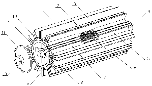
[0022] The sand roller of a polishing machine of the present invention is realized in this way. When in use, the transmission rod is connected with the drive motor shaft of the polishing machine through the transmission sleeve (4), so that the transmission rod and the drive motor shaft are coaxial, and the other end of the drive rod is fixed On the support table of the polishing machine, the drive motor shaft rotates to drive the transmission shaft (12) to rotate through the transmission sleeve (4), and the transmission shaft (12) is transmitted through the rectangular protrusion on the support plate (8) to drive the support plate ( 8) Rotate synchronously, so that the main sand roller (7) and the auxiliary sand roller (5) rotate, and when rotating, the corresponding emery cloth belt (1), the first brush (3) and the second brush (2) rotate , move the plate to fit the emery cloth belt (1) step by step, and perform polishing and grinding. When the arc surface needs to be polished...


PUM


Abstract

The invention discloses a grinding roller of a polishing machine. According to the grinding roller, two separated grinding roller bodies are connected through a connection rod, and are rotated synchronously through a drive shaft, the connection rod is bent by adjusting the distance between the two separated grinding roller bodies, an arc groove is formed between the two grinding roller bodies, andthus plates can be polished and ground. The grinding roller of the polishing machine is characterized in that two supporting plates are arranged in the main grinding roller body and located at the two ends of the main grinding roller body separately; each supporting plate is formed by combining a center circular ring and four supporting arms arranged on the outer side wall of the center circularring at equal angles; the center circular rings and the main grinding roller body are coaxial; a rectangular protrusion is arranged on the inner side wall of each center circular ring, and the rectangular protrusions on the two supporting plates are located on the same straight line; a plurality of mounting grooves are formed in the outer side walls of the main grinding roller body and distributedalong the circumference and extend in the axial direction of the main grinding roller body; every three mounting grooves fall into one group, and the widths of the three mounting grooves of each group are gradually decreased; a chuck is disposed at the end face of one end of the main grinding roller body.

Description

technical field [0001] The invention relates to an emery roller for a polishing machine, which relates to an emery roller for polishing the surface of a plate when processing and polishing a plate, and belongs to the field of wood processing. In particular, it relates to two separated emery rollers connected by a connecting rod, the two emery rollers are rotated synchronously through the transmission shaft, and the connecting rod is bent by adjusting the distance between the two emery rollers. An arc-shaped groove is formed between the rollers, and the emery roller is used for polishing and grinding the plate. Background technique [0002] At present, in the production and processing of furniture, it is necessary to polish and polish some special-shaped parts. Usually, when processing special-shaped parts, the surface milling is first carried out through the machining center, so that the blank of the special-shaped contour is processed, and then the special-shaped parts are ...

Claims


Application Information

Patent Timeline
Patent Type & Authority Applications(China)
IPC IPC(8): B24B21/00B24B21/16B24B21/18
CPCB24B21/004B24B21/008B24B21/16B24B21/18
Inventor 不公告发明人
Owner 安徽省汇金木业股份有限公司
Why Eureka
Try Eureka