Tensioning floating type flexible joint and design method thereof

A technology of flexible joints and design methods, applied in computer-aided design, calculation, special data processing applications, etc., can solve problems such as friction accumulation, affecting robot performance, high cost, etc., to achieve improved stress state, excellent performance, and reduced drive force demand effect

Active Publication Date: 2018-12-18
HARBIN INST OF TECH
View PDF10 Cites 21 Cited by
  • Summary
  • Abstract
  • Description
  • Claims
  • Application Information

AI Technical Summary

Problems solved by technology

On articulated robots, friction can be accumulated, affecting the performanc

Method used


Image

  • Tensioning floating type flexible joint and design method thereof
  • Tensioning floating type flexible joint and design method thereof
  • Tensioning floating type flexible joint and design method thereof

Examples


Embodiment 1

[0027] A method for designing a tensioned floating flexible joint. The steps are as follows:

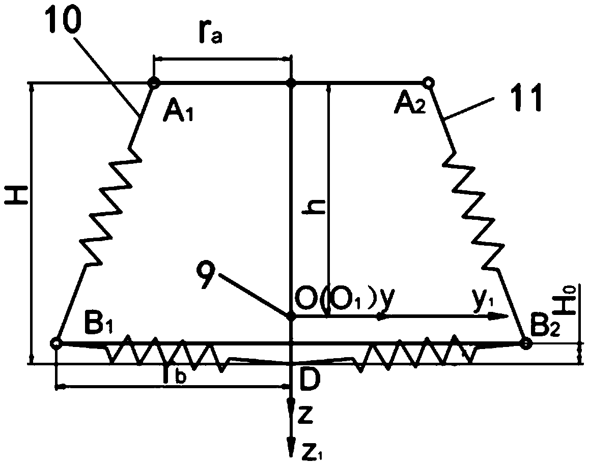
[0028] For a tensioned floating flexible joint, zero stiffness means one degree of freedom, high stiffness means restraint, and low stiffness means pseudo degree of freedom. This stiffness anisotropy can be used to design the degree of freedom of a tensioned floating flexible joint. Specifically, the rotational stiffness should be designed to be much lower than the translational stiffness. Under the same driving torque, the low-rigidity part is easier to produce greater displacement than the high-rigidity part. The greater the difference in stiffness, the greater the difference in motion. There are 6 degrees of freedom in the tensioned floating flexible joint, which are expressed as: x: x translation, y: y translation, z: z translation, Roll, θ: pitch, ψ: yaw;

[0029] 1. Decoupling of degrees of freedom

[0030] When the influence of external force and internal force on stiffness is n...

Embodiment 2

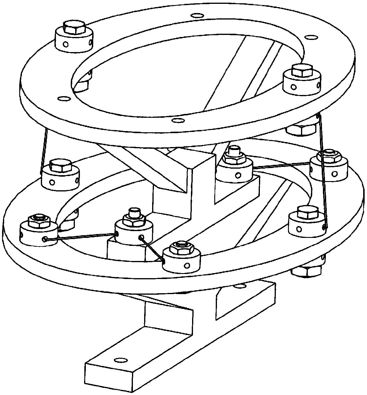
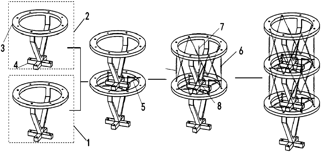
[0041] Such as Figure 1-2 As shown, a tensioned floating flexible joint includes a base platform, a driven platform, and 16 sets of tension elements. The upper structure of the base platform and the lower structure of the driven platform are connected by multiple sets of horizontal tension elements. The upper structure of the platform and the upper structure of the driven platform are connected by multiple sets of axial tension elements, so that the driven platform can be suspended and supported. The multiple sets of axial tension elements provide vertical downward pulling force, and multiple sets of horizontal The tension element provides vertical upward tension to resist, so that the driven platform can float around the base platform without direct mechanical contact. The basic platform and the driven platform are of pan-footed structure. These tension elements are used as outriggers. Springs, pneumatic muscles, shape memory alloys, steel wire ropes or elastic wires can be us...


PUM


Abstract

The invention relates to a tensioning floating type flexible joint and a design method thereof. The flexible joint comprises a foundation platform, a driven platform and a plurality of tension elementsets. The upper face structure of the foundation platform is connected with the lower face structure of the driven platform by the horizontal tension element sets. The upper face structure of the foundation platform is connected with the upper face structure of the driven platform by the axial-directional tension element sets. In this way, the driven platform can be supported in a suspension mode. The axial-directional tension element sets provide pulling force vertical downwards. The horizontal tension element sets provide tension force vertical upwards for confronting, and therefore the driven platform can rotate around the foundation platform in a suspension mode without direct mechanical contact. The design method comprises degree of freedom decoupling and uniform dimensionalization stiffness anisotropic design index. The joint can reduce or even eliminate mechanical abrasion and friction caused by mechanical contact, can improve the stress state of the structure, and can reduce driving force demands.

Description

Technical field [0001] The invention mainly relates to a tensioned floating flexible joint and its design method. Background technique [0002] At present, rigid joints are basically used in traditional robots and mechanical arms. There will be mechanical friction between rigid joints, which will reduce the robot's driving efficiency, stability and other performance. Although high-precision bearings can be used to reduce friction, friction still exists. On multi-joint robots, friction will be accumulated, which will affect the performance of the robot. In addition, high-precision bearings often represent high costs. Summary of the invention [0003] The purpose of the present invention is to provide a tensioned floating flexible joint and a design method thereof. This tensioned floating flexible joint can realize floating rotation without direct rigid contact, and can replace traditional rotating hinges, such as rotating joints and tigers. K hinge, spherical hinge, etc. [0004...

Claims


Application Information

Patent Timeline
IPC IPC(8): B25J17/00B25J17/02G06F17/50
CPCB25J17/00B25J17/0225G06F30/17G06F2119/06
Inventor 姜洪洲陈炳兴
Owner HARBIN INST OF TECH
Why Eureka
Try Eureka