Foam plastic recycling device

A recovery device and technology of foam plastics, applied in plastic recycling, recycling technology, presses, etc., can solve the problems of foam waste occupying a large space and inconvenient transportation, and achieve convenient transportation, space saving, and reduction of occupied space Effect

Inactive Publication Date: 2018-12-18
泸州市龙马潭区鑫泉泡沫塑料有限责任公司
View PDF0 Cites 6 Cited by
  • Summary
  • Abstract
  • Description
  • Claims
  • Application Information

AI Technical Summary

Problems solved by technology

[0003] During the processing of foam plastics, scraps will be produced. At present, these scraps are collected manually and bound and fixed, and then the waste is transported away. However, due to manual bundling, the foam waste occupies a large space, which is inconvenient. transportation

Method used


Image

  • Foam plastic recycling device
  • Foam plastic recycling device

Examples


Embodiment 1

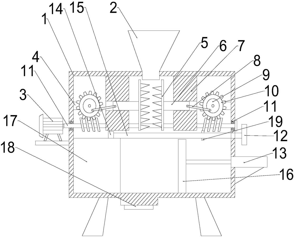
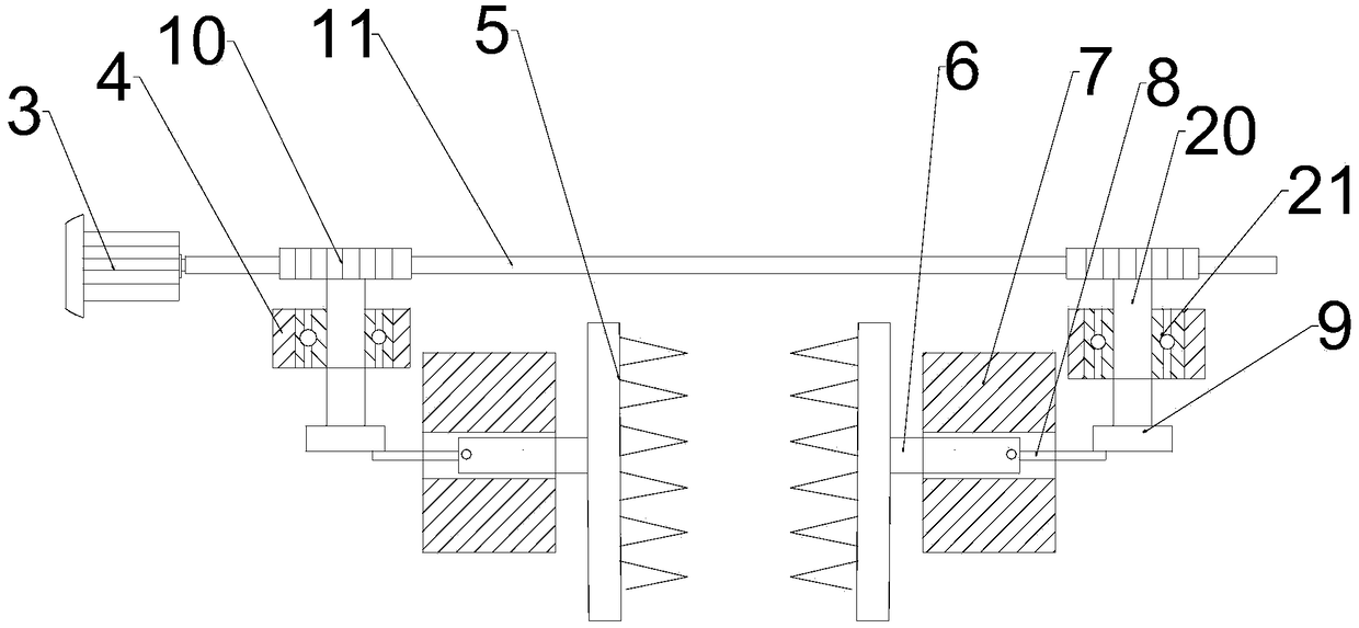
[0027] see Figure 1~2 , a foam recovery device, comprising a box body 1, the top of the box body 1 is fixedly connected with a feed cylinder 2, the top inside of the box body 1 is fixed with a symmetrically placed limiting plate 7 on both sides, and the two sides of the box body 1 are fixed with The fixed plate 4 placed symmetrically, the fixed plate 4 is equipped with a rotatable rotating shaft 20, a gear 10 is fixed on one end of the rotating shaft 20, a rotating wheel 9 is fixed on the other end of the rotating shaft 20, a motor 3 is fixedly installed on the left outer wall of the box body 1, and a motor 3 The output shaft is fixedly connected to one end of the worm 11, and the worm 11 is rotatably connected to both sides of the casing 1. The shaft of the worm 11 is provided with two opposite worm teeth matched with the gear 10 and symmetrical along the center of the casing 1. The gear 10 is meshed with the worm gear, the rotating wheel 9 is hinged with one end of the ecce...

Embodiment 2

[0030] see Figure 1~2 , a foam recovery device, comprising a box body 1, the top of the box body 1 is fixedly connected with a feed cylinder 2, the top inside of the box body 1 is fixed with a symmetrically placed limiting plate 7 on both sides, and the two sides of the box body 1 are fixed with The fixed plate 4 placed symmetrically, the fixed plate 4 is equipped with a rotatable rotating shaft 20, a gear 10 is fixed on one end of the rotating shaft 20, a rotating wheel 9 is fixed on the other end of the rotating shaft 20, a motor 3 is fixedly installed on the left outer wall of the box body 1, and a motor 3 The output shaft is fixedly connected to one end of the worm 11, and the worm 11 is rotatably connected to both sides of the casing 1. The shaft of the worm 11 is provided with two opposite worm teeth matched with the gear 10 and symmetrical along the center of the casing 1. The gear 10 is meshed with the worm gear, the rotating wheel 9 is hinged with one end of the ecce...

Embodiment 3

[0034] see Figure 1~2, a foam recovery device, comprising a box body 1, the top of the box body 1 is fixedly connected with a feed cylinder 2, the top inside of the box body 1 is fixed with a symmetrically placed limiting plate 7 on both sides, and the two sides of the box body 1 are fixed with The fixed plate 4 placed symmetrically, the fixed plate 4 is equipped with a rotatable rotating shaft 20, a gear 10 is fixed on one end of the rotating shaft 20, a rotating wheel 9 is fixed on the other end of the rotating shaft 20, a motor 3 is fixedly installed on the left outer wall of the box body 1, and a motor 3 The output shaft is fixedly connected to one end of the worm 11, and the worm 11 is rotatably connected to both sides of the casing 1. The shaft of the worm 11 is provided with two opposite worm teeth matched with the gear 10 and symmetrical along the center of the casing 1. The gear 10 is meshed with the worm gear, the rotating wheel 9 is hinged with one end of the eccen...


PUM


Abstract

The invention relates to the field of foam recycling, and discloses a foam plastic recycling device. The device comprises a box body. A feeding cylinder is fixedly connected to the top of the box body, limiting plates which are symmetrically arranged are fixed to two sides of the top end in the box body, fixed plates which are symmetrically arranged are fixed to two sides of the interior of the box body, and a motor is fixedly arranged on the outer wall of the left side of the box body. According to the foam plastic recycling device, through the arrangement of the limiting plates and the fixedplates and the cooperation of the motor, a worm, a rotating shaft, a crank connecting rod mechanism, a meshing plate and a movable door, a meshing plate can be driven to move in a reciprocating modethrough the motor, foam waste is cut off, then the meshed foam waste is extruded through a hydraulic cylinder principle and is compacted, and then the effects of convenient transportation and space saving in the foam waste recycling process are achieved.

Description

technical field [0001] The invention relates to the field of foam recovery, in particular to a foam recovery device. Background technique [0002] Foam plastic is a kind of polymer material formed by dispersing a large number of gas micropores in solid plastic. It has the characteristics of light weight, heat insulation, sound absorption, shock absorption, etc., and its dielectric performance is better than that of matrix resin. It has a wide range of uses. Through the molding process, it can be processed into foam plastics of various shapes and thicknesses according to needs. [0003] During the processing of foam plastics, scraps will be produced. At present, these scraps are collected manually and bound and fixed, and then the waste is transported away. However, due to manual bundling, the foam waste occupies a large space, which is inconvenient. transportation. Therefore, we are in urgent need of a recovery device that can reduce the space occupied by foam waste and fa...

Claims


Application Information

Patent Timeline
IPC IPC(8): B29B17/04B29B17/00B30B1/32B30B15/00
CPCB29B17/00B29B17/0412B29B2017/044B30B1/32B30B15/00Y02W30/62
Inventor 肖启
Owner 泸州市龙马潭区鑫泉泡沫塑料有限责任公司
Why Eureka
Try Eureka