A water rescue robot

A technology of rescue robots and single-chip microcomputers, which is applied in the fields of water rescue, ship safety, etc., can solve the problems of both rescuers and drowning people being killed, the inability to guarantee the personal safety of rescuers, and long time-consuming, etc., so as to improve rescue efficiency, The effect of reducing stress and increasing operating speed

Active Publication Date: 2019-10-08
六安维奥智能科技有限公司
View PDF6 Cites 0 Cited by
  • Summary
  • Abstract
  • Description
  • Claims
  • Application Information

AI Technical Summary

Problems solved by technology

[0002] The current water rescue is only limited to relying on manpower and some simple equipment to go into the water to search and rescue the drowning person. The above-mentioned existing technical solutions not only take a long time and are inefficient, but also cannot guarantee the personal safety of the rescuers, and sometimes there are rescues. Situations where both the person and the drowning person die

Method used


Image

  • A water rescue robot
  • A water rescue robot
  • A water rescue robot

Examples


Embodiment 1

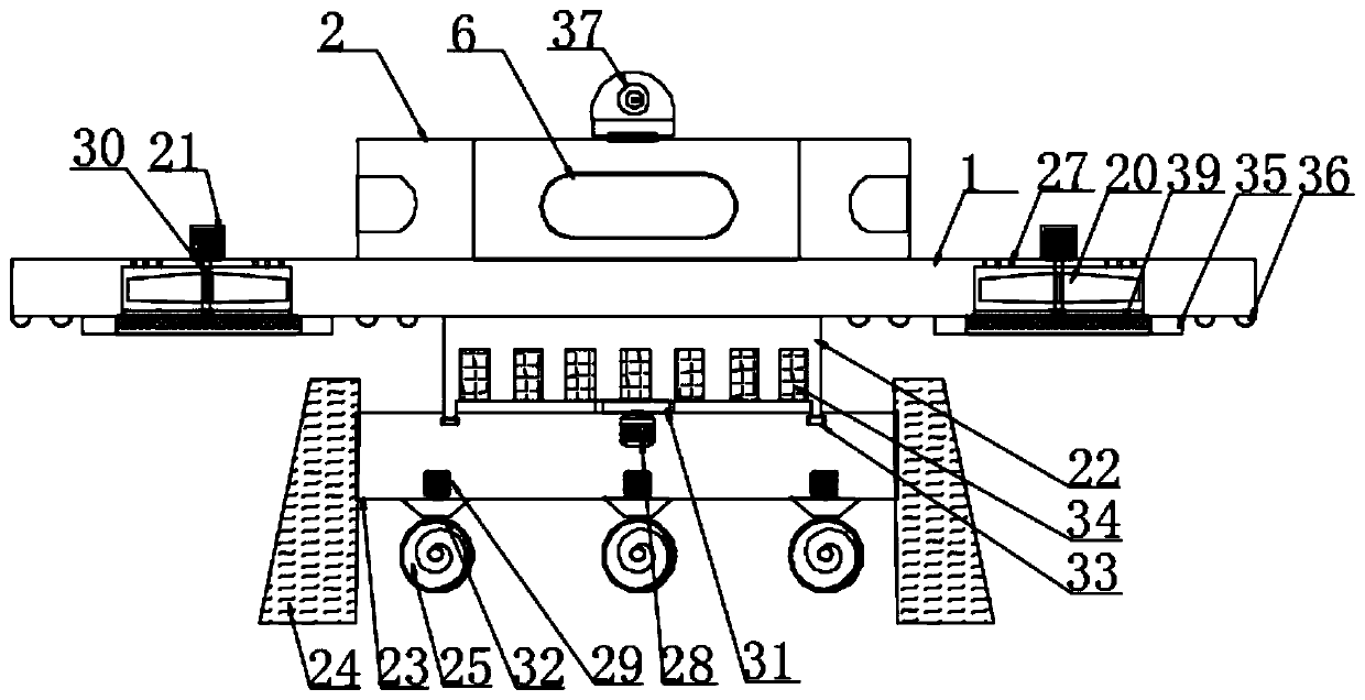
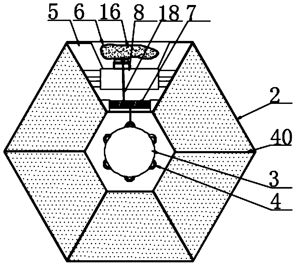
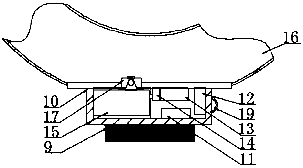
[0028] according to Figure 1-6 The shown water rescue robot includes a floating board 1, which is characterized in that: the top of the floating board 1 is provided with a housing 2, and the shaft center of the housing 2 is provided with a fixed pile 3, and the outer side of the fixed pile 3 is A first hanging ring 4 is provided, and a storage room 5 is provided in the housing 2, and a spray channel 6 is provided in the storage room 5, and two symmetrically distributed shaft sleeves are fixedly connected in the storage room 5, and the two A storage roller 7 is arranged between the two bushings, an air cannon 8 is fixedly connected in the storage chamber 5, a rubber plug 9 is arranged at the output end of the air cannon 8, and a rubber plug 9 is fixedly connected to the other side of the rubber plug 9. A sealed box 10, the sealed box 10 is provided with a collision sensor 11, one side of the collision sensor 11 is provided with a single-chip microcomputer 12, one side of the s...

Embodiment 2

[0033]The bottom of the floating plate 1 is provided with a groove, and an impeller 20 is arranged in the groove, a rotating shaft 30 is arranged at the axis of the impeller 20, and a first motor 21 is arranged at the top of the rotating shaft 30. The floating plate 1 A connecting frame 22 is arranged at the center of the bottom axis, and a support frame 23 is provided at the bottom of the connecting frame 22, and crawler belt assemblies 24 are provided on both sides of the support frame 23, and a power mechanism is provided at the bottom of the support frame 23. The power mechanism includes a propeller 25, a water collecting cover 26 is arranged on the outside of the propeller 25, the rotation of the first motor 21 makes the rotating shaft 30 rotate, the rotation of the impeller 20 makes the floating plate 1 obtain buoyancy, and crawler belt assemblies 24 are arranged on both sides of the bracket 23, The robot can run smoothly on land, and the track assembly 24 can prevent the...


PUM


Abstract

The invention discloses a water rescue robot, including floating plates, A shell is arranged on the top of the floating plate, a fixed pile is arranged at the axis of the shell, a first hanging ring is arranged on the outside of the fixed pile, a receiving chamber is arranged in the shell, a jet passage is arranged in the receiving chamber, two axle sleeves with symmetrical distribution are fixedly connected in the receiving chamber, and a receiving drum is arranged between the two axle sleeves. a storage chamber is arranged in the shell., An air cannon is fixedly connected with that a receiving chamber, The air cannon ejected rubber plugs, A rubber plug with a sealing box and an airbag lifebuoy is projected out of the spray passage, ,under the pressure of the air cannon, the collision sensor is vibrated and sends the signal to the single-chip microcomputer for processing, the single-chip microcomputer receives the signal and controls the igniter to ignite in the airbag gas generator,triggers the reaction of the airbag gas generator to generate nitrogen gas to be filled from the inflation valve, and the airbag life buoy expands rapidly to meet the rescue requirement.

Description

technical field [0001] The invention relates to the field of rescue equipment, in particular to a water rescue robot. Background technique [0002] The current water rescue is only limited to relying on manpower and some simple equipment to go into the water to search and rescue the drowning person. The above-mentioned existing technical solutions not only take a long time and are inefficient, but also cannot guarantee the personal safety of the rescuers, and sometimes there are rescues. A situation where both the person and the drowning person are killed. [0003] Therefore, it is necessary to invent a kind of water rescue robot to solve the above problems. Contents of the invention [0004] The object of the present invention is to provide a kind of rescue robot on water, by being provided with storage room, the air cannon is fixedly connected in the storage room, and the air cannon shoots out the rubber plug, and the rubber plug is thrown out of the injection channel w...

Claims


Application Information

Patent Timeline
Patent Type & Authority Patents(China)
IPC IPC(8): B63C9/00
Inventor 陈杰
Owner 六安维奥智能科技有限公司
Why Eureka
Try Eureka