Anti-adhesion plate and manufacturing method thereof

A manufacturing method and anti-sticking plate technology, applied in ion implantation plating, metal material coating process, coating, etc., can solve the problems of high coating cost, high maintenance cost and cleaning cost, and low service life of the anti-sticking plate , to achieve the effect of reducing coating cost, good density and reducing maintenance cost

Active Publication Date: 2018-12-18
SHENZHEN CHINA STAR OPTOELECTRONICS TECH CO LTD
View PDF6 Cites 7 Cited by
  • Summary
  • Abstract
  • Description
  • Claims
  • Application Information

AI Technical Summary

Problems solved by technology

[0005] The purpose of the present invention is to provide an anti-sticking plate and its manufacturing method to solve the problems of low service life of the anti-sticking plate, high maintenance cost and cleaning cost, and high coating cost in the prior art.

Method used


Image

  • Anti-adhesion plate and manufacturing method thereof
  • Anti-adhesion plate and manufacturing method thereof
  • Anti-adhesion plate and manufacturing method thereof

Examples


Embodiment Construction

[0026] The following description of the embodiments refers to the accompanying drawings to illustrate specific embodiments in which the invention may be practiced. The directional terms mentioned in the present invention, such as "up", "down", "front", "back", "left", "right", "top", "bottom", etc., are only for reference to the attached drawings. direction. Therefore, the directional terms used are used to illustrate and understand the present invention, but not to limit the present invention.

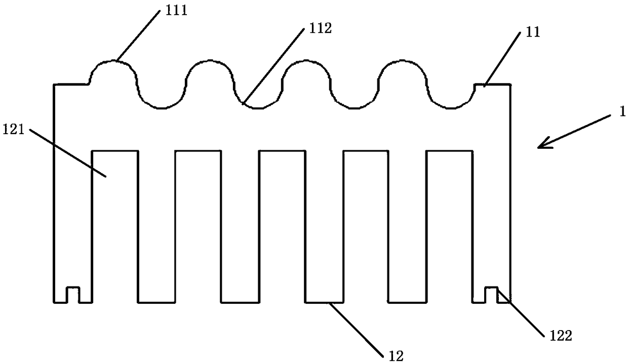
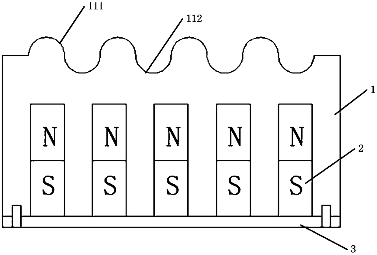
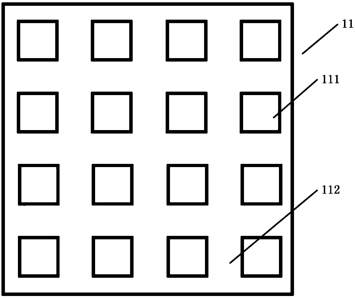
[0027] Such as figure 1 , figure 2 As shown, an anti-seating board includes: a board body 1 ; a plurality of magnets 2 ; and a rear cover 3 . The plate body 1 includes an anti-anti-surface 11 and a back surface 12 opposite to the anti-anti-surface 11 . Several protrusions 111 and grooves 112 are disposed around each protrusion 111 on the anti-impact surface 11 of the board body 1 . The back surface 12 of the board body 1 is provided with a plurality of installation grooves 121 ...


PUM

PropertyMeasurementUnit
angleaaaaaaaaaa

Abstract

The invention discloses an anti-adhesion plate. The anti-adhesion plate comprises a plate body, a plurality of magnets and a rear cover. The anti-adhesion face of the plate body is provided with a plurality of protrusions and grooves formed around the protrusions. A plurality of mounting grooves are formed in the back side of the anti-adhesion plate, and permanent magnets or electromagnets are assembled in the mounting grooves. The anti-adhesion plate has the beneficial effects that a magnetic field with certain intensity is added into the anti-adhesion plate to increase the moving distance ofplasma, so that sputtered atoms stay on the surface of the anti-adhesion plate after hitting against argon ions repeatedly, the sputtered atoms adhere to the surface of the anti-adhesion plate more uniformly, the membranous compactness is better, the service life of the anti-adhesion plate is prolonged, particle generation is restrained, and accordingly, the coating cost is reduced, and the maintenance cost of the anti-adhesion plate is reduced.

Description

technical field [0001] The invention relates to the field of vacuum sputtering, in particular to an anti-sticking plate and a manufacturing method thereof. Background technique [0002] Vacuum sputtering is a process in which electrons are accelerated to the substrate under the action of an electric field and collide with argon atoms, ionizing a large number of argon ions and electrons, and the electrons fly to the substrate. Under the action of the electric field, the argon ions accelerate the bombardment of the target, sputtering out a large number of target atoms, and the neutral target atoms (or molecules) are deposited on the substrate to form a film, and finally achieve the purpose of coating the substrate surface. However, during the above-mentioned vacuum sputtering process, sputtered target atoms or large-sized particles will eventually fly to the inner wall surface of the sputtering equipment, affecting the cleaning of the sputtering equipment. Therefore, it is ne...

Claims


Application Information

Patent Timeline
Patent Type & Authority Applications(China)
IPC IPC(8): C23C14/34
CPCC23C14/34
Inventor 张军
Owner SHENZHEN CHINA STAR OPTOELECTRONICS TECH CO LTD
Why Eureka
Try Eureka