Tightening system of concrete rectangular column formwork and construction method of concrete column

A concrete column and concrete technology, applied in the direction of formwork/formwork/work frame, column, pier column, etc., can solve the problems of time-consuming, low efficiency, and time-consuming

Inactive Publication Date: 2018-12-18
上海生睿住宅工业有限公司
View PDF5 Cites 10 Cited by
  • Summary
  • Abstract
  • Description
  • Claims
  • Application Information

AI Technical Summary

Problems solved by technology

[0003] The above process needs to pass the tension bolts through the wooden formwork, and the tension bolts must be in a horizontal state to ensure that the support force on the formwork is relatively uniform, so it takes a certain amount of time for the staff to align, which is time-consuming and inefficient.

Method used


Image

  • Tightening system of concrete rectangular column formwork and construction method of concrete column
  • Tightening system of concrete rectangular column formwork and construction method of concrete column
  • Tightening system of concrete rectangular column formwork and construction method of concrete column

Examples


Embodiment 1

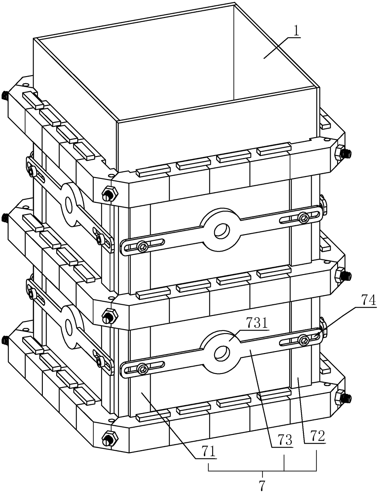
[0049] A kind of construction method of concrete column, with reference to figure 1 , including the following steps:

[0050] S1: Formwork 1 is installed, and the standardized concrete formwork 1 is spliced ​​to the outside of the column reinforcement, and the space enclosed by the formwork 1 is closed, and the closed interior forms a concrete pouring space;

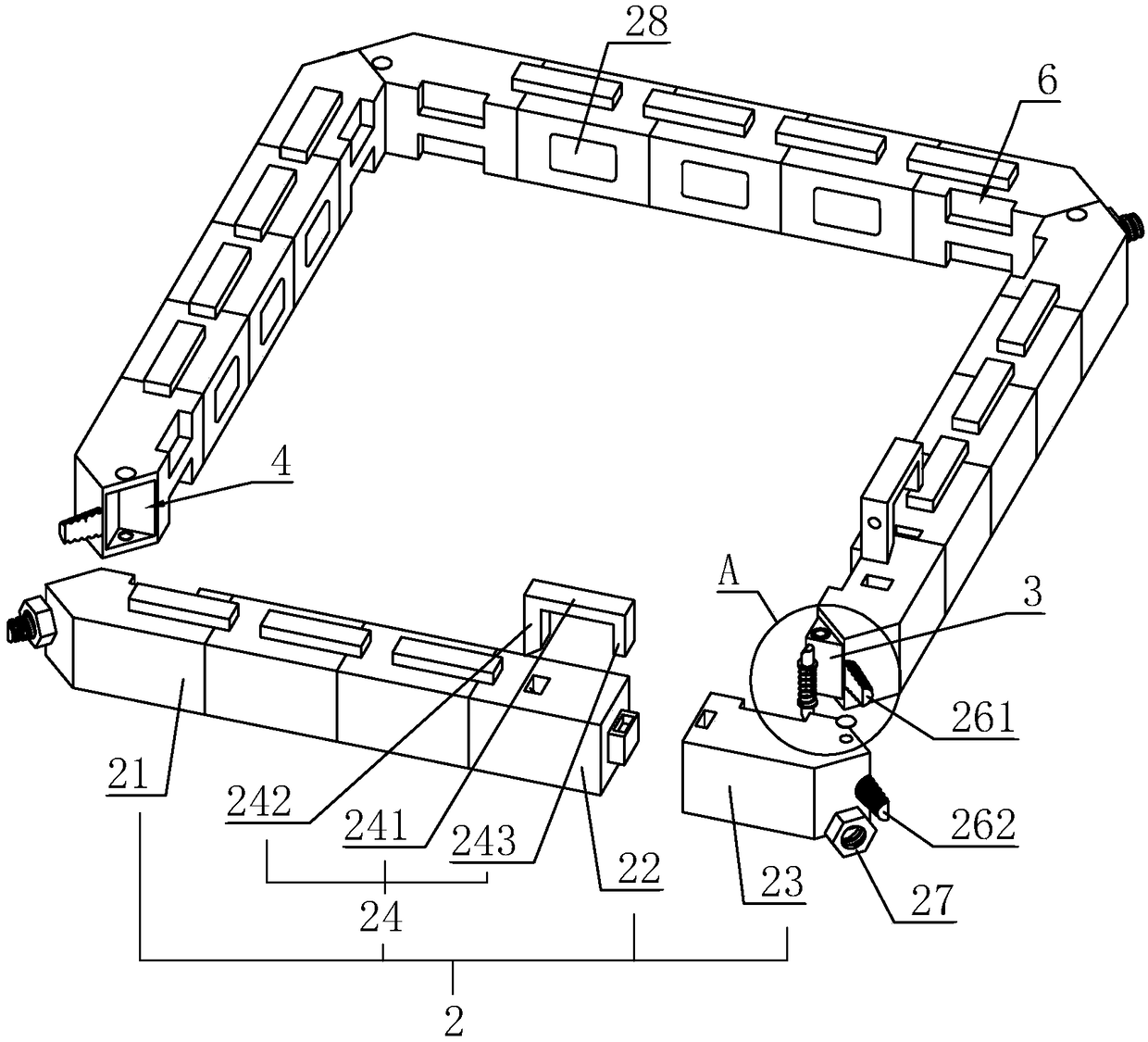
[0051] S2: Reinforce formwork 1, surround the four sides of the column formwork 1 with the pressing device, then insert the connecting component 7 into the pressing device, and then install another ring of pressing device, so as to be installed on the column formwork 1 alternately , and installed from the bottom of the column to the top of the column;

[0052] S3: Concrete pouring, pouring concrete into the pouring space, and pouring the area close to the formwork 1 first, and then pouring the steel bar area in the middle, and vibrating with a vibrating rod;

[0053]S4: dismantling, when the concrete reaches a certain ...

Embodiment 2

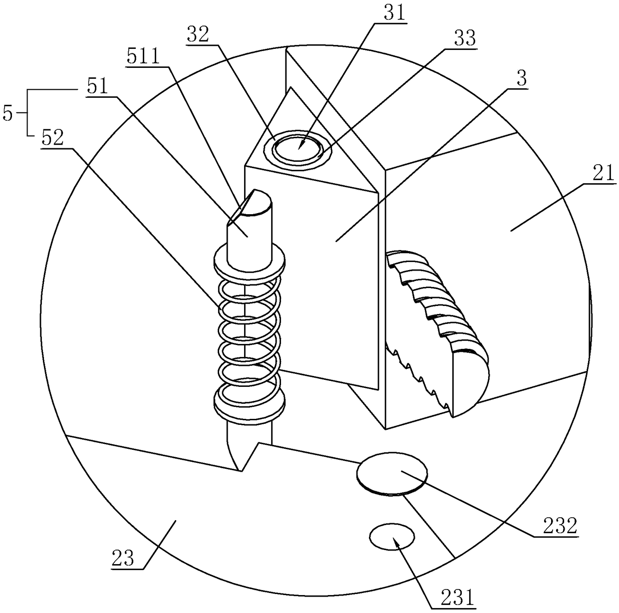
[0071] A fastening system for concrete rectangular column formwork, refer to Figure 5 The difference from Embodiment 1 is that: one end of the bottom of the block 3 that abuts against the slot 4 is provided with a locking slot 34 that is inclined upward, and the bottom of the slot 4 of the second fixing part 23 is provided with a locking slot 34 The slideways 233 are parallel and have the same cross section, and the opening of the slideway 233 is on the same level as the opening of the locking groove 34 . The second fixed part 23 is provided with a control hole 234 that is vertical and stepped and communicates with the slideway 233. The cross section of the end of the control hole 234 connected to the slideway 233 is larger than the cross section on the surface of the second fixed part 23. In the control hole A buffer chamber 235 is defined at the joint between the slideway 234 and the slideway 233 .

[0072] The locking assembly 5 includes a locking lever 81, an operating l...


PUM


Abstract

The invention discloses a tightening system of a concrete rectangular column formwork and a construction method of a concrete column, and relates to the technical field of concrete building. The system comprises an abutting device mounted on a side wall of a formwork around the concrete column, the abutting device comprises four cross bars which are connected in sequence, are closely adjacent tothe formwork and are provided with isosceles right-angled triangle-shaped two ends, clamping blocks which are disposed on the ends of the cross bars and faced to an oblique surface of one side of theformwork, clamping grooves which are formed in the other ends of the cross bars, faced to the oblique surface of the side of the formwork and clamped and cooperated with the clamping blocks and locking assemblies which connect the clamping grooves and the clamping blocks, and the locking assemblies protrude from the surfaces of the cross bars. By fixing the positions of the clamping blocks and theclamping grooves through the locking assemblies, the fixing between the adjacent cross bars is achieved, thereby achieving the purpose of fixing the concrete formwork, the operation is simple and convenient, and a large amount of time is saved, thereby greatly improving the efficiency of fixing the formwork.

Description

technical field [0001] The invention relates to the technical field of concrete buildings, more specifically, it relates to a fastening system for a concrete rectangular column formwork and a construction method for a concrete column. Background technique [0002] At present, the traditional concrete column formwork mostly uses wooden panels, wooden back corrugations, dragon skeletons and pull bolts. When using, the wooden square back corrugations are first fixed on the wooden panels, and then the wooden panels are erected to surround the column reinforcement, and The dragon frame is erected, and the stay bolts are passed through the wooden formwork and fixed on the dragon frame. [0003] The above process needs to pass the tension bolts through the wooden formwork, and the tension bolts must be in a horizontal state to ensure that the support force on the formwork is relatively uniform, so it takes a certain amount of time for the staff to align, which is time-consuming and...

Claims


Application Information

Patent Timeline
Patent Type & Authority Applications(China)
IPC IPC(8): E04G13/02E04C3/34
CPCE04C3/34E04G13/02
Inventor 陈云仝伟
Owner 上海生睿住宅工业有限公司
Why Eureka
Try Eureka