Hydraulic differential mechanism with built-in steel ball

A differential mechanism and steel ball technology, applied in the direction of extracting the undisturbed core device, earthwork drilling and mining, etc., can solve the problems of long time consumption, complicated design of the pressurization mechanism, and many processes

Pending Publication Date: 2018-12-18
EXPLORATION TECH RES INST OF CHINESE ACADEMY OF GEOLOGICAL SCI
View PDF0 Cites 0 Cited by
  • Summary
  • Abstract
  • Description
  • Claims
  • Application Information

AI Technical Summary

Problems solved by technology

[0002] In order to grasp the underground geological conditions, the real and reliable underground rock formation data are directly obtained by drilling (well) coring. With the continuous deepening of core drilling (well), more and more complex formations are encountered. When drilling and taking cores in complex formations such as loose, broken, poorly cemented, weak, and easily eroded, the core recovery rate is extremely low, and even cores cannot be collected
For this reason, relevant researchers have developed a forced coring tool. Through a pressurized differential mechanism, the core claws are forced to close and hold the core tightly, so as to solve the problem of low core collection rate in complex formations.
[0003] In the prior art, forced coring tools include single-action double-tube forced coring drills, double-action double-tube forced coring drills, and rope forced coring drills. Drilling tools adopt the method of dropping steel balls from the hole (well) mouth, and use the steel balls for pressure transmission; however, the way of throwing the balls from the hole needs to start the pump twice before and after, the operation process is cumbersome, there are many procedures, and the steel balls fall It takes a long time to enter the bottom of the well. As the drilling continues to deepen, it will take longer and longer, adding too much auxiliary time
The upper part of the rope forced core drilling tool is equipped with a salvage mechanism and a suspension mechanism. The steel ball cannot pass through, so it can only be pressurized by hydraulic pressure. The switch between the flushing fluid channel and the closed circuit is controlled by the hydraulic control reversing valve to realize the differential However, due to the relatively complicated design of its pressurizing mechanism, it has high requirements for hydraulic and dynamic sealing, and it will be difficult to realize the reversing action of the waterway if there is a slight pressure relief. In addition, due to the many movements of parts, the reliability of use is poor Once the movement is disordered, it will be impossible to judge whether the forced coring has been completed. If the drill is easily lifted when drilling in complex formations, it is very likely to cause loose and broken formation cores to fall off, resulting in the loss of first-hand geological data.

Method used


Image

  • Hydraulic differential mechanism with built-in steel ball
  • Hydraulic differential mechanism with built-in steel ball
  • Hydraulic differential mechanism with built-in steel ball

Examples


Embodiment Construction

[0021] The present invention will be further described below in conjunction with the accompanying drawings and specific embodiments.

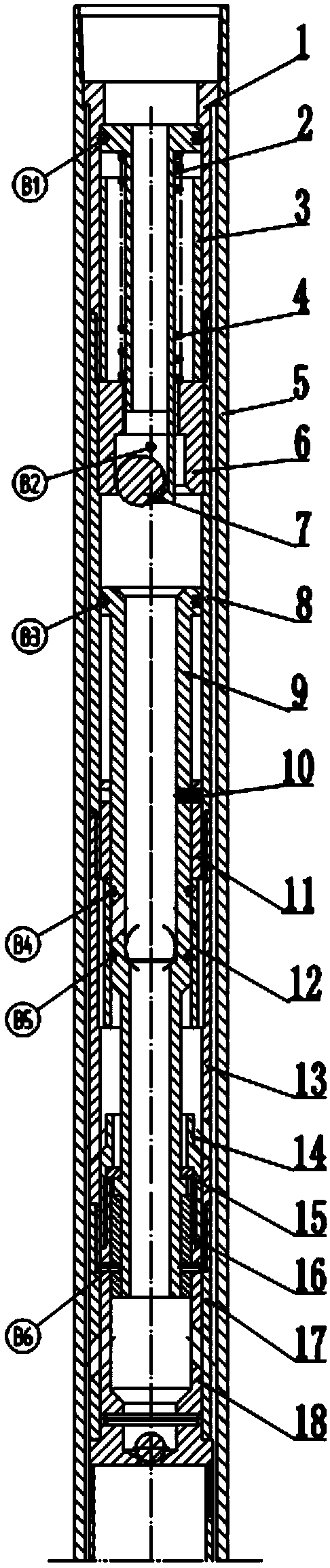
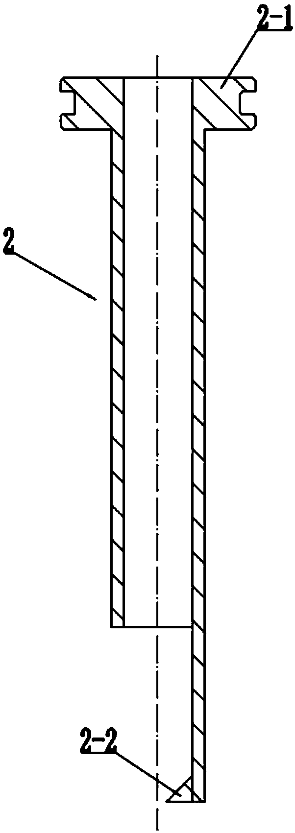
[0022] See Figure 1, figure 2 , the present invention is a built-in steel ball hydraulic differential mechanism of a double-tube core drilling tool, which is placed in the outer tube 5 of the core drilling tool and consists of a ball-throwing part and a differential part. The ball-throwing part is arranged Above the differential part, the pitching part is provided with a pitching piston jacket 1, a pitching piston 2, a pitching piston stopper 3, a pitching spring 4, a steel ball chamber 6 and a pressure holding steel ball 7; on the inner wall of the outer tube 5 of the core drilling tool; the pitching piston 2 is placed in the pitching piston outer casing 1, which is a hollow cylinder, the upper end of which is provided with a first pressure bearing plate 2-1, and the lower end passes through the steel ball chamber 6. The bottom of the throwi...


PUM


Abstract

The invention provides a hydraulic differential mechanism with a built-in steel ball. The mechanism comprises a ball throwing part and a differential part. The ball throwing part is arranged on the differential part. A ball throwing piston cover, a ball throwing piston, a ball throwing piston limiting sleeve, a ball throwing spring, a steel ball chamber and a pressure building steel ball. The ballthrowing piston cover is embedded in the inner wall of the outer pipe of a rope wire line core driller. The ball throwing piston is arranged in the ball throwing piston cover and is of a hollow cylinder. A first pressure bearing disc is arranged on the upper end of the ball throwing piston and the lower end of the ball throwing piston passes through the steel ball chamber. An inward wedge-shapedboss is arranged at the bottom of the ball throwing piston. The ball throwing spring is assembled between the first pressure bearing disc and the steel ball chamber in a pre-compression manner. The ball throwing piston limiting sleeve sleeves the exterior of the ball throwing spring. According to the invention, by combining the way of internally arranging of the steel ball and the ball throwing pressure building, compulsory coring working is finished. The objectives of improving recovery factor and drilling-in and coring efficiency of complex stratums which are loosened, broken, poor in cementing properties, weak and easy to wawshout during drilling-in coring are achieved.

Description

technical field [0001] The invention relates to a double-tube core drilling tool, in particular to a built-in steel ball hydraulic differential mechanism of the double-tube core drilling tool. Background technique [0002] In order to grasp the underground geological conditions, the real and reliable underground rock formation data are directly obtained by drilling (well) coring. With the continuous deepening of core drilling (well), more and more complex formations are encountered. When cores are drilled in complex strata such as loose, broken, poorly cemented, weak, and easily eroded, the core recovery rate is extremely low, and even cores cannot be collected. For this reason, relevant researchers have developed a forced coring tool. Through a pressurized differential mechanism, the core claws are forced to close and hold the core tightly, so as to solve the problem of low core recovery rate in complex formations. [0003] In the prior art, forced coring tools include sin...

Claims


Application Information

Patent Timeline
IPC IPC(8): E21B25/00
CPCE21B25/00
Inventor 李鑫淼尹浩李宽梁健孙建华王志刚刘秀美王文
Owner EXPLORATION TECH RES INST OF CHINESE ACADEMY OF GEOLOGICAL SCI
Why Eureka
Try Eureka