Anchor hole construction technology

A construction process and bolt hole technology, which is applied in the installation of bolts, infrastructure engineering, construction, etc., can solve the problems of difficulty in forming holes, difficulty in drilling and constructing high-quality bolt holes, etc., to achieve rapid hole forming and improve drilling Efficient construction and simple operation

Active Publication Date: 2019-12-13
北京京能地质工程有限公司
View PDF7 Cites 0 Cited by
  • Summary
  • Abstract
  • Description
  • Claims
  • Application Information

AI Technical Summary

Problems solved by technology

[0005] However, it is more difficult to form holes in soft ground such as clay stratum, sand stratum, crushed pebble stratum, and miscellaneous fill stratum, and it is more difficult to drill high-quality bolt holes.

Method used


Image

  • Anchor hole construction technology
  • Anchor hole construction technology
  • Anchor hole construction technology

Examples


Embodiment 1

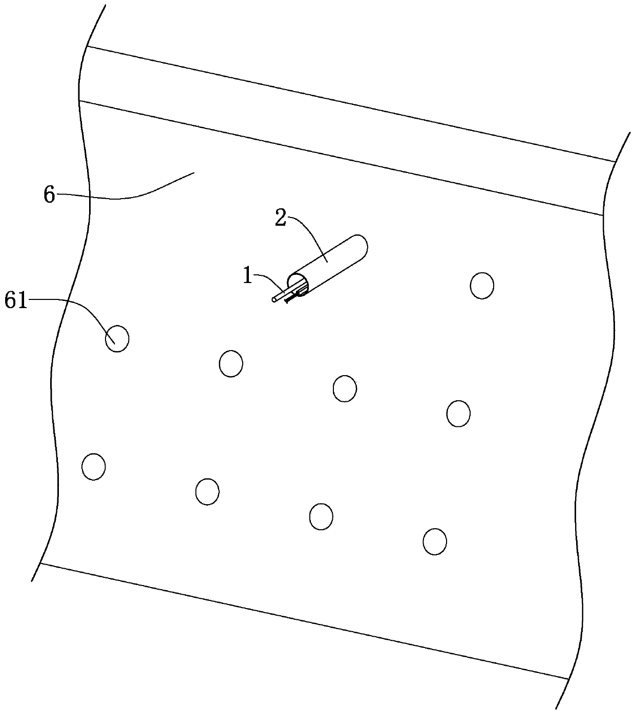
[0048] A bolt hole construction process, such as figure 1 As shown, the anchor rod hole 61 is drilled with a vibratory compaction hole forming device on the slope of the formation 6 that needs to be reinforced.

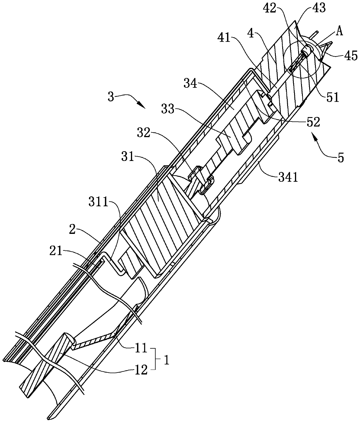
[0049] Such as figure 2 As shown, the vibrating compaction hole former includes a Luoyang shovel 1, which includes a U-shaped shovel body 11 and a long-rod shovel handle 12, and two adjacent shovel handles 12 are threaded. When the drilling depth of the anchor hole construction process is small, the number of 12 shovel handles is appropriately reduced to facilitate the use of Luoyang shovel 1 during drilling.

[0050] Such as figure 2 As shown, the casing 2 is sheathed on the outside of the shovel body 11, and the Luoyang shovel 1 slides along the side wall of the casing 2.

[0051] Such as figure 2 As shown, a plurality of connecting rods are welded and fixed at one end of the inner side of the casing 2, and a vibrator 3 is fixed on the connecting rods. The v...

Embodiment 2

[0070] A kind of bolt hole construction technique, differs from embodiment 2 in that, as Figure 4 As shown, the outer side of the sleeve 2 is covered with a positioning plate 7, on which the first horizontal bubble 71 parallel to the axis of the sleeve 2 is cemented and fixed, and on the positioning plate 7 is fixed a second horizontal bubble 71 perpendicular to the axis of the sleeve 2. Two levels of bubbles 72.

[0071] When determining the angle of the drill bit 4, set the positioning plate 7 on the outer side of the casing 2 near the end of the vibrator 3, and adjust the position of the casing 2 when drilling the anchor hole 61 with a horizontal axis using a vibration compacting hole forming device. , observe the horizontal bubble in the first horizontal bubble 71 at the same time, when the bubble in the first horizontal bubble 71 is in the middle, it can be confirmed that the position of the casing 2 is accurate; when drilling the bolt hole 61 with a vertical axis, obser...

Embodiment 3

[0073] A kind of bolt hole construction technique, differs from embodiment 2 in that, as Figure 5 As shown, the positioning plate 7 is provided with four relief holes 73 that are evenly distributed on the positioning plate 7 in the circumferential direction, and the axes of the relief holes 73 are parallel to the axis of the casing 2 . The positioning plate 7 is provided with a fixed frame 8, the fixed frame 8 includes a screw rod 82 passing through the relief hole 73, and the outer side of the screw rod 82 is welded on the positioning plate 7 for guiding the screw rod 82 to move along the axis of the casing 2 The limit tube 81, the end of the screw rod 82 away from the vibrator 3 is welded and fixed with a knob 83 whose diameter is larger than that of the relief hole 73.

[0074] After determining the position of the anchor hole 61, place the fixing frame 8 on the opening of the anchor hole 61, turn the screw rod 82 to insert the screw rod 82 into the formation 6, and the li...


PUM


Abstract

The invention discloses an anchor rod hole construction process and belongs to the field of support engineering. The anchor rod hole construction process aims to realize soft foundation layer drilling. The key points of the technical scheme are that an anchor rod hole is drilled through a vibration extrusion hole forming device; the vibration extrusion hole forming device comprises a luoyang shovel, and a sleeve is arranged on the outer side of the luoyang shovel in a sleeved mode. One end of the sleeve is fixedly connected with a vibrator, and a drill bit is fixedly arranged at the end, extending out of the sleeve, of a vibrator. The construction process of an anchor rod hole comprises the steps of determining a hole position; adjusting the drilling and building angle, extruding and forming a hole, extracting the stratum substance, and forming the anchor rod hole. According to the anchor rod hole construction process, the problem that the forming holes in soft ground layer is difficult is solved.

Description

technical field [0001] The invention relates to the field of support engineering, in particular to a construction technique for bolt holes. Background technique [0002] Bolt support refers to a reinforcement and support method used in surface engineering such as slopes and deep foundation pits, as well as underground chambers such as tunnels and stopes. The bolt support effect is good, the construction is simple and the construction speed is fast. [0003] When carrying out the construction of the support structure, it is often necessary to drill holes to fix the anchor rods. The main hole-forming equipment includes Luoyang shovel, ordinary auger drilling rig, casing drilling rig, etc. The use environment of these equipment has certain restrictions, and the formation is different and the drilling depth is different. At the same time, the hole-forming efficiency and quality vary greatly. [0004] The Chinese invention patent application document with the application public...

Claims


Application Information

Patent Timeline
Patent Type & Authority Patents(China)
IPC IPC(8): E21D20/00E02D5/74
CPCE02D5/74E21D20/003
Inventor 孙金龙蔡冠军刘永祥岳江潮
Owner 北京京能地质工程有限公司
Why Eureka
Try Eureka