Marine piston-free engine and drive method thereof
An engine and piston-less technology, applied to internal combustion piston engines, combustion engines, machines/engines, etc., can solve problems such as low reliability, high noise, and heavy weight, and achieve the effects of improving work efficiency, reducing failures, and improving kinetic energy
- Summary
- Abstract
- Description
- Claims
- Application Information
AI Technical Summary
Problems solved by technology
Method used
Image


Examples
Embodiment 1
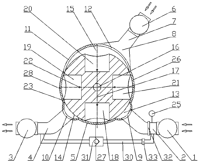
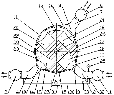
[0063] The engine described in the present invention is a marine diesel engine, which must be placed in water for use, wherein the water inlet 9 is immersed in water, and the exhaust port 11 and the air inlet 12 are placed in the air. When the engine needs to work, the drive system drives the rotating shaft 16 to rotate along the direction in which the water inlet cavity 13, the drainage cavity 14, and the air cavity 15 are arranged sequentially on the surface of the housing 5, thereby driving each cylinder in the housing 5 along the direction of the water inlet. The cavity 13 , the drainage cavity 14 , and the air cavity 15 rotate in the order in which they are arranged sequentially on the surface of the casing 5 .
[0064] Now take the working process of cylinder A18 as an example to explain the working principle of the engine:
[0065] When the cylinder A18 rotates to a position corresponding to the air inlet 12, gas enters the air chamber 15 through the air inlet 12 under ...
Embodiment 2
[0075] The engine described in the present invention is a marine diesel engine, which must be placed in water for use, wherein the water inlet 9 is immersed in water, and the exhaust port 11 and the air inlet 12 are placed in the air. When the engine needs to work, the rotating shaft 16 is manually rotated so that the rotating shaft 16 rotates in the direction in which the water inlet cavity 13, the drainage cavity 14, and the air cavity 15 are arranged sequentially on the surface of the housing 5, thereby driving each cylinder body in the housing. 5 to rotate along the direction in which the water inlet cavity 13, the drainage cavity 14, and the air cavity 15 are arranged sequentially on the surface of the housing 5. Because rotating shaft 16 is connected with the driving shaft of water inlet pump 1, the driving shaft of drainage pump 3, and the driving shaft of air pump 6 through transmission mechanism 24, the rotational power of rotating shaft 16 can be transmitted to the ot...
PUM
 Abstract
Description
Claims
Application Information