
Novel explosion-proof oxygen supercharger

A supercharger, oxygen technology, applied in the mechanical field, can solve the problems of poor sealing performance, oxygen explosion, etc., and achieve the effect of reducing the high temperature environment

Inactive Publication Date: 2018-12-18
威海威高海盛医用设备有限公司
View PDF6 Cites 2 Cited by
  • Summary
  • Abstract
  • Description
  • Claims
  • Application Information

AI Technical Summary

Problems solved by technology

[0002] Oxygen boosters mostly use piston oil-free air compressors to replace the oxygen boosters of multi-tower PSA oxygen generators. The structure of this equipment is a single-cylinder attribute. There is no gas sealing isolation device. During the operation of the piston, part of the oxygen will penetrate into the crankcase from the piston edge of the cylinder. The shaft seal of the crankcase of the oil-free air compressor is a product structure with poor sealing performance. Once the gas enters Crankcase, the gas will leak out through the shaft seal. According to the test, the oxygen booster based on the structure of the piston oil-free air compressor can reach more than 10% of the oxygen leakage rate in the initial stage of operation. When the oxygen booster continues When the operation time exceeds one month, the oxygen leakage rate can reach more than 15%. Because there are many moving parts inside the crankcase, the crankshaft will generate high temperature during the rotation of the crankcase, and the gas compression process will also generate high temperature. The action in the crankcase can easily cause the internal parts of the crankcase to reach the ignition temperature, resulting in an oxygen explosion. At present, there have been many similar explosion cases in China

Method used


Image

  • Novel explosion-proof oxygen supercharger

Examples


Embodiment 1

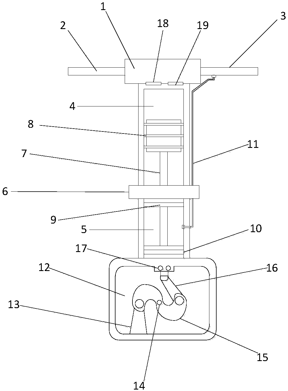
[0008] Such as figure 1 As shown, a novel explosion-proof oxygen supercharger according to the present invention adopts a technical scheme comprising an air chamber 1, an exhaust connecting pipe 2, an intake connecting pipe 3, a cylinder 4, a transition cylinder 5, and an interlayer 6 , crankshaft connecting rod 7, piston head 8, crankcase 12, base 13, shaft seal 14, crankshaft 15, linkage rod 16, oil injection hole 17, exhaust valve 18, intake valve 19; wherein cylinder 4 is a hollow cylinder The upper part of the cylinder 4 is connected to the air chamber 1; the air chamber 1 is a cuboid, and the inside is a cavity, the left side of the air chamber 1 is connected to the exhaust connecting pipe 2, and the right side is the intake connecting pipe 3; the cylinder 4 and the air chamber 1 There are exhaust valve 18 and intake valve 19 at the connection, so that the cylinder 4 communicates with the air chamber 1; the exhaust valve 18 and the intake valve 19 are one-way valves, the...


PUM


Abstract

The invention relates to a novel explosion-proof oxygen supercharger. According to the technical scheme, the novel explosion-proof oxygen supercharger comprises an air chamber, an exhaust connecting pipe, an air inlet connecting pipe, an air cylinder, a transition air cylinder, a partition layer, a crankshaft connecting rod, a piston head, a crankshaft box, a base, a shaft seal, a crankshaft, a linkage rod, an oil injection hole, an exhaust valve and an air inlet valve. The top and the bottom of the transition air cylinder are each provided with a tetrafluorohydrazine seal shaft sleeve, the crankshaft connecting rod penetrates the tetrafluorohydrazine graphite seal shaft sleeves, the tetrafluorohydrazine graphite seal shaft sleeves can exert the lubricating seal effect in the crankshaft connecting rod running process, and oxygen in the air cylinder can be prevented from leaking into the transition air cylinder or leakage gas in the transition air cylinder is prevented from entering thecrankshaft box. According to the test, the oxygen leakage rate of the device can be controlled to the level below 0.5%, and the accident potentials of oxygen leakage and explosion prevention can be thoroughly avoided.

Description

technical field [0001] The invention belongs to the field of machinery and relates to a novel explosion-proof oxygen booster. Background technique [0002] Oxygen boosters mostly use piston oil-free air compressors to replace the oxygen boosters of multi-tower PSA oxygen generators. The structure of this equipment is a single-cylinder attribute. There is no gas sealing isolation device. During the operation of the piston, part of the oxygen will penetrate into the crankcase from the piston edge of the cylinder. The shaft seal of the crankcase of the oil-free air compressor is a product structure with poor sealing performance. Once the gas enters Crankcase, the gas will leak out through the shaft seal. According to the test, the oxygen booster based on the structure of the piston oil-free air compressor can reach more than 10% of the oxygen leakage rate in the initial stage of operation. When the oxygen booster continues When the operation time exceeds one month, the oxygen ...

Claims


Application Information

Patent Timeline
IPC IPC(8): F04B39/00F04B39/02F04B39/10F04B39/12
CPCF04B39/00F04B39/02F04B39/10F04B39/122F04B39/128
Inventor 刘彦林荆一峰林伟
Owner 威海威高海盛医用设备有限公司
Learn More