
Aspheric surface parameter error interference measuring method combining laser differential confocal positioning

A differential confocal and interferometric measurement technology, applied in the direction of measuring devices, optical devices, instruments, etc., can solve the problems that the relative position of the measured surface and part of the compensation lens cannot be determined, achieve fast measurement speed and improve measurement accuracy Effect

Active Publication Date: 2018-12-18
BEIJING INSTITUTE OF TECHNOLOGYGY
View PDF13 Cites 24 Cited by
  • Summary
  • Abstract
  • Description
  • Claims
  • Application Information

AI Technical Summary

Problems solved by technology

[0005] In order to solve the problem that the relative position of the measured surface and part of the compensation lens cannot be determined when the compensation interferometry is used to measure the aspheric parameter error in the prior art, the aspheric parameter error interferometry method combined with laser differential confocal positioning disclosed by the present invention is to be solved The technical problem is: combined with laser differential confocal positioning to determine the relative position of the measured surface and part of the compensation lens, and then improve the measurement accuracy of the surface parameter error of the aspheric surface, and can achieve non-contact, full aperture, fast speed and high precision. The measurement has the advantages of no scanning device and simple structure

Method used


Image

  • Aspheric surface parameter error interference measuring method combining laser differential confocal positioning
  • Aspheric surface parameter error interference measuring method combining laser differential confocal positioning
  • Aspheric surface parameter error interference measuring method combining laser differential confocal positioning

Examples


Embodiment 1

[0048] The aspheric surface parameter error interferometry method combined with laser differential confocal positioning is realized in the following way:

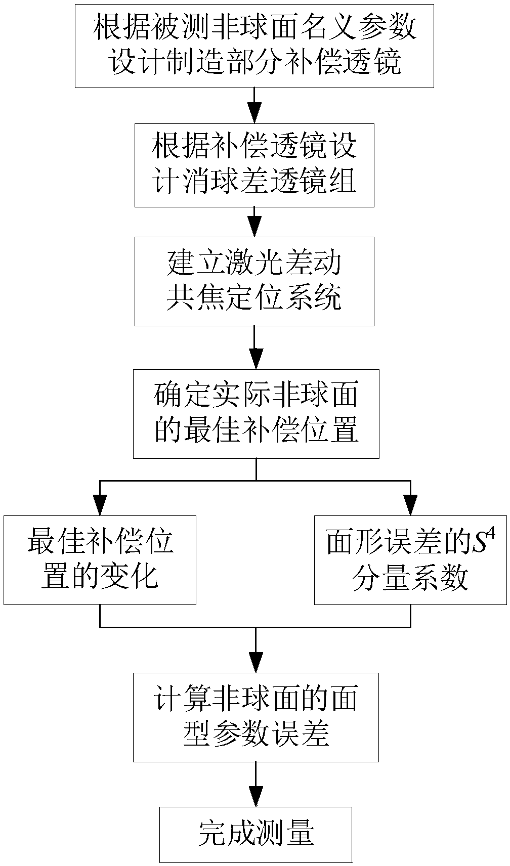
[0049] The process flow of establishing an aspheric surface parameter error interferometry method combined with laser differential confocal positioning is as attached figure 1 As shown, the specific implementation steps are:

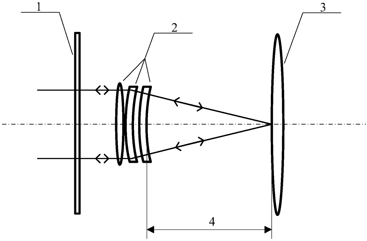
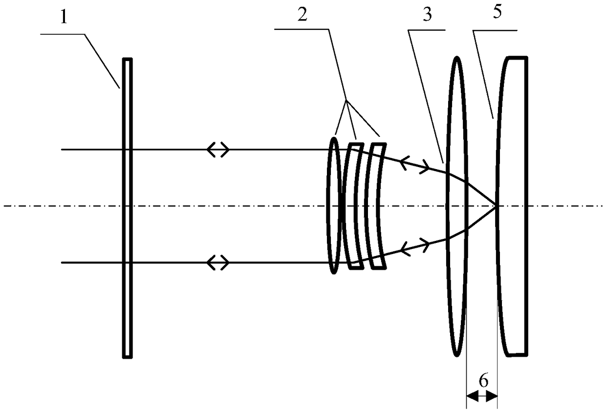
[0050] Step 1: Obtain the nominal parameters of the measured aspheric surface, use the obtained nominal parameters of the measured aspheric surface, and combine the optical design software to design the partial compensation lens 3, obtain the design parameters of the designed partial compensation lens 3, and construct an interferometric measurement of the aspheric surface parameter error system model.

[0051] Step 1.1: Get the nominal parameters of the measured aspheric surface.

[0052] Obtaining the nominal parameters of the measured aspheric surface includes the caliber of the measured aspheric ...


PUM


Abstract

The invention discloses an aspheric surface parameter error interference measuring method combining laser differential confocal positioning and belongs to the field of aspheric surface measurement. Animplementation method comprises the following steps: acquiring nominal parameters of a measured aspheric surface, and by utilizing the acquired nominal parameters of the measured aspheric surface andcombining optical design software, designing and processing a part-compensating lens and aplanatic lenses; according to the part-compensating lens and the aplanatic lenses, establishing an aspheric surface parameter error interference measuring system combining the laser differential confocal positioning; obtaining an optimal compensation position change by utilizing the system; measuring a surface figure change between the measured aspheric surface and an ideal aspheric surface, and calculating a coefficient of a quartic component of the surface figure change; and according to a simultaneousequation set, calculating a surface figure parameter error of the aspheric surface, thus measurement on the surface figure parameter error of the aspheric surface is realized. The method disclosed bythe invention can improve accuracy of measurement on the surface figure parameter error of the aspheric surface, realizes non-contact, full-aperture, fast and high-accuracy measurement and has the advantages of no scanning device and simple structure.

Description

technical field [0001] The invention relates to an aspherical surface parameter error interferometric measurement method combined with laser differential confocal positioning, belonging to the field of aspheric surface measurement. Background technique [0002] The surface parameters of an aspheric surface include the vertex curvature radius and the quadric surface constant. These two parameters together determine the shape characteristics of the aspheric surface. Among them, the radius of curvature of the vertex not only affects the profile of the aspheric surface, but also determines the basic properties of the aspheric surface, which in turn affects the aberration and imaging quality of the optical system; and the quadric surface constant It is the classification basis of aspheric surface. Accurate measurement of surface parameter errors is very important for the processing and assembly of optical aspheric surfaces. Usually, the surface profile of the measured surface c...

Claims


Application Information

Patent Timeline
Patent Type & Authority Applications(China)
IPC IPC(8): G01B11/24G01B11/00
Inventor 胡摇郝群赵维谦陶鑫李腾飞
Owner BEIJING INSTITUTE OF TECHNOLOGYGY
Learn More