
Connection structure of urea liquid level sensor and joint for vehicle

A technology of liquid level sensor and urea for vehicles, which is applied in the direction of liquid level indicators, instruments, and engine lubrication, etc. It can solve problems such as inconvenient installation, affecting the sealing performance of joints and orifices, and complex manufacturing and processing of external joints and orifices.

Inactive Publication Date: 2018-12-18
FOSHAN CHUANDONG MAGNETOELECTRICITY +1
View PDF6 Cites 1 Cited by
  • Summary
  • Abstract
  • Description
  • Claims
  • Application Information

AI Technical Summary

Problems solved by technology

[0004] The purpose of the present invention is to solve the problem of fixed communication between the external joint and the orifice in the prior art by means of internal thread and external thread, which makes the production and processing of the external joint and the orifice complicated, and the installation will be difficult due to different pitches. Inconvenient, and when installing the sealing ring, it is easy to be damaged by the screw teeth, and the integrity of the sealing ring cannot be guaranteed, thus affecting the sealing between the joint and the orifice. A vehicle urea level sensor and Joint connection structure

Method used


Image

  • Connection structure of urea liquid level sensor and joint for vehicle
  • Connection structure of urea liquid level sensor and joint for vehicle
  • Connection structure of urea liquid level sensor and joint for vehicle

Examples


Embodiment Construction

[0017] The following will clearly and completely describe the technical solutions in the embodiments of the present invention with reference to the accompanying drawings in the embodiments of the present invention. Obviously, the described embodiments are only some, not all, embodiments of the present invention.

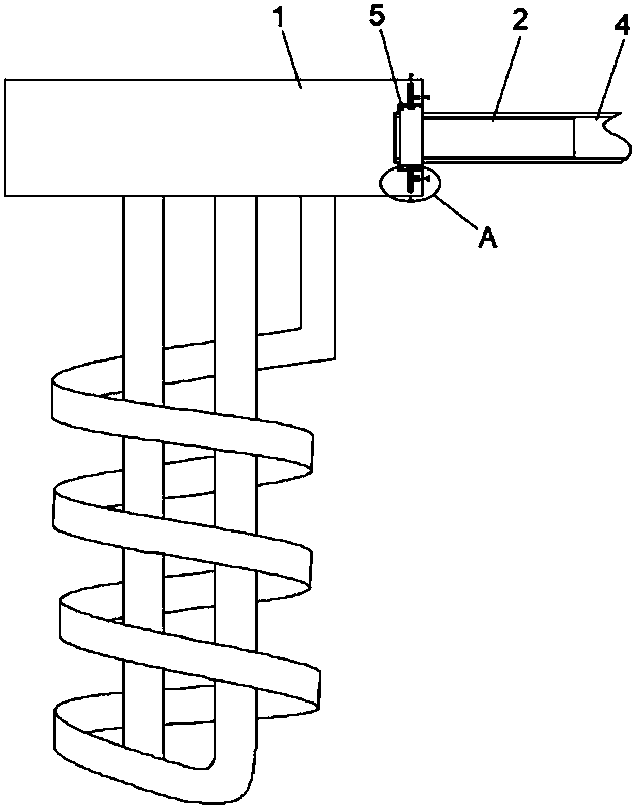
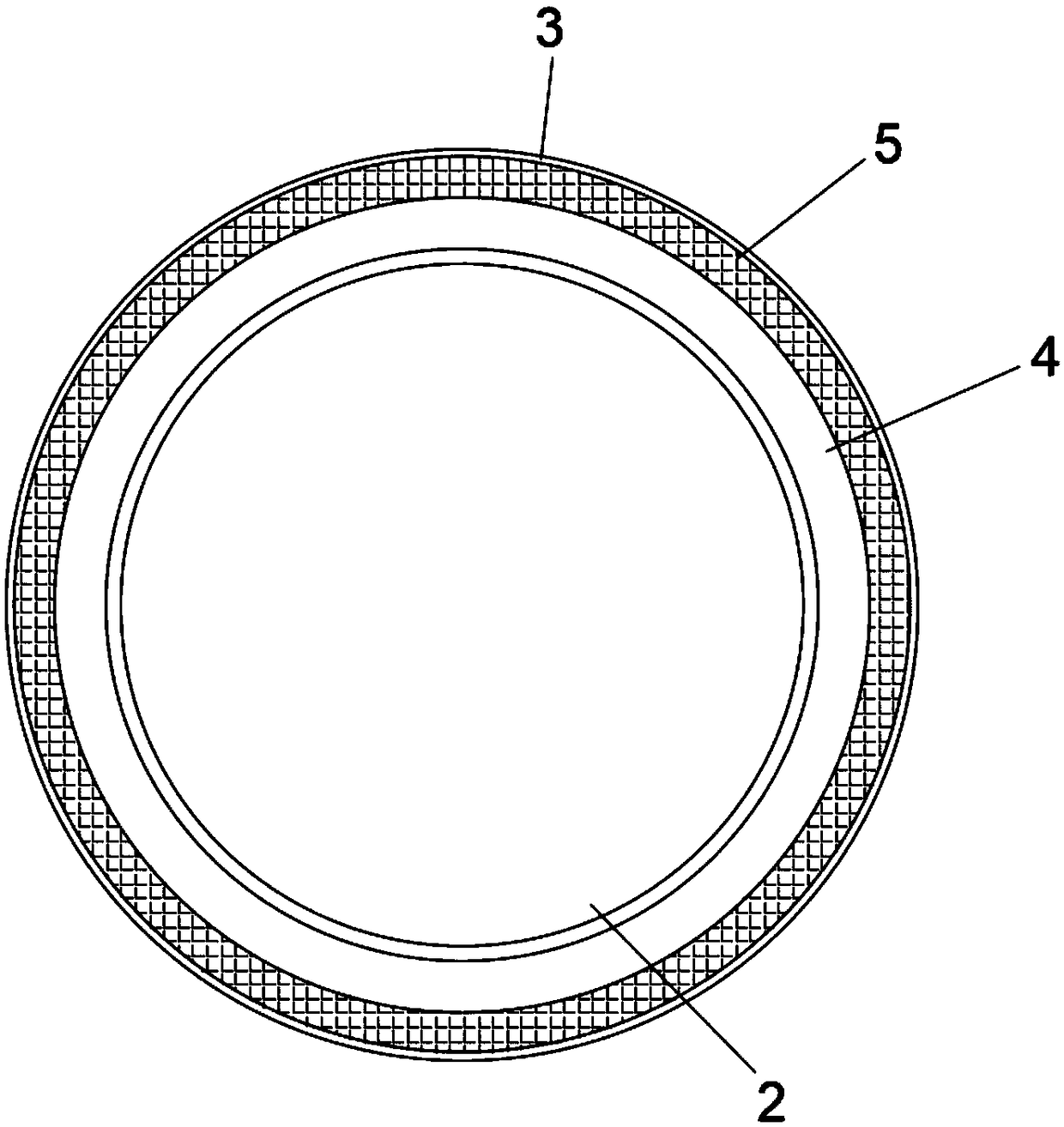
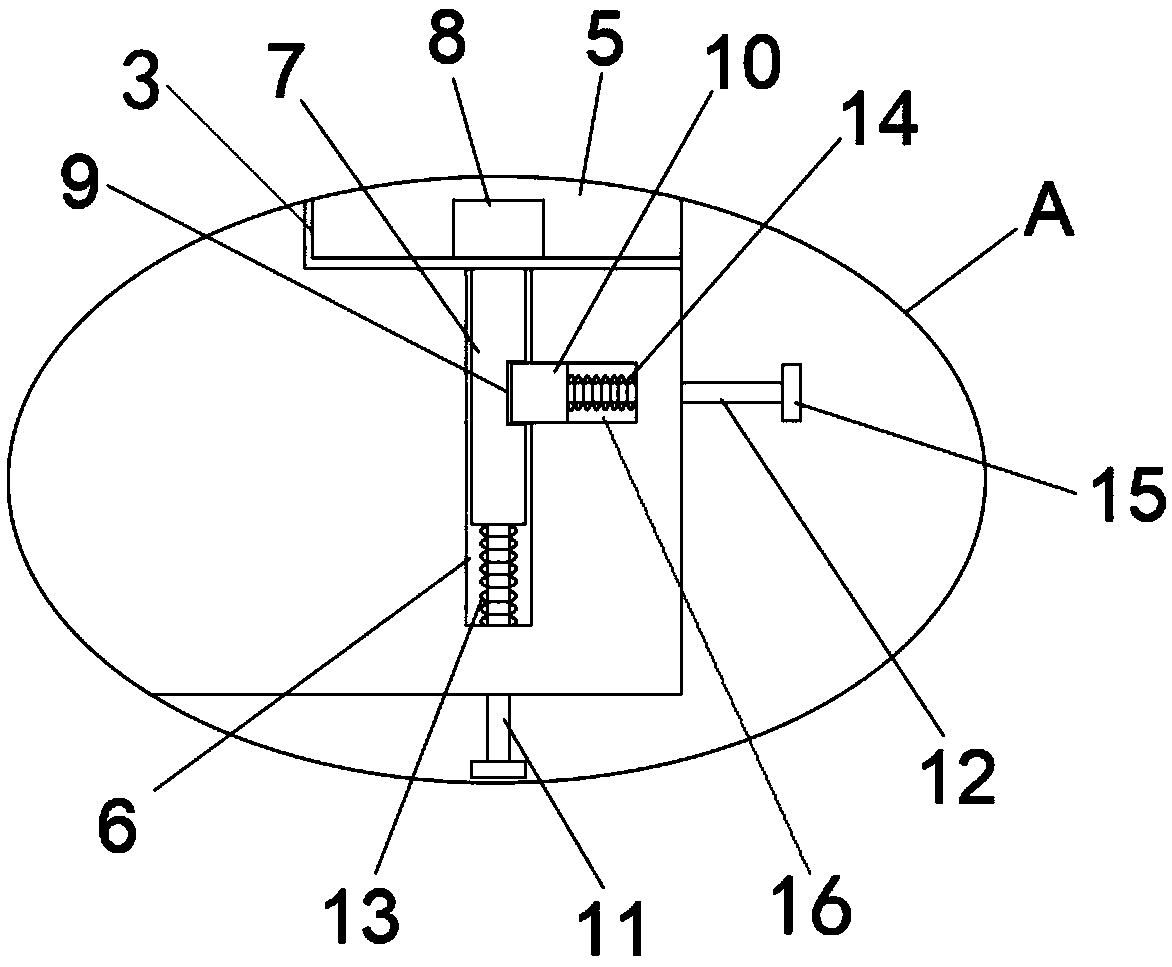
[0018] refer to Figure 1-3 , a connection structure between a urea liquid level sensor and a joint for a vehicle, comprising a liquid level sensor fixing seat 1, an orifice 2 is fixedly connected to the side wall of the liquid level sensor fixing seat 1, and an external joint 4 is sleeved outside the orifice 2 One end of the external joint 4 is provided with an annular sealing ring 5. The annular sealing ring 5 is made of rubber material, and the sealing effect is better. Groove 3, the diameter of the annular slot 3 is equal to the diameter of the annular sealing ring 5, and the inner wall of the annular slot 3 is also provided with an annular sealing groove for use...


PUM


Abstract

The invention discloses a connection structure of a urea liquid level sensor and a joint for a vehicle. The connection structure comprises a liquid level sensor fixing seat; the side wall of the liquid level sensor fixing seat is fixedly connected with a hole opening; the hole opening is sleeved with the outer joint; one end of the outer joint is sleeved with an annular sealing ring; an annular inserting groove matched with the annular sealing ring to be used is formed in the side wall of the liquid level sensor fixing seat; the diameter of the annular inserting groove is equal to the sum of the diameter of the outer joint and the diameter of the annular sealing ring; two first grooves are symmetrically formed in the side wall of the annular inserting groove; a first clamping block is slidably connected into each first groove; first clamping grooves are formed in the positions, corresponding to the first clamping blocks, of the surface of the annular sealing ring correspondingly; and second clamping grooves are formed in the surfaces of the first clamping blocks correspondingly. The outer joint and the hole opening do not need to be subjected to threaded machining, mounting and connecting are convenient, the sealing effect of the sealing ring is not affected, and the sealing effect is good.

Description

technical field [0001] The invention relates to the technical field of urea tank liquid level sensors, in particular to a connection structure between a vehicle urea liquid level sensor and a joint. Background technique [0002] Commercially used urea aqueous solution is called AdBlue, which is non-toxic, clean, not easy to catch fire, and has no danger of explosion. It is used to chemically react with nitrogen oxides to reduce nitrogen oxide emissions from diesel engines. The container used as the urea aqueous solution is called the urea tank. The urea tank in the prior art is provided with a liquid level sensor, and the fixing seat of the liquid level sensor is provided with a plurality of orifices, and the orifices are used to communicate with external joints. , the external joints in the prior art usually use the front end of the joint directly, and the external joint is fixedly connected with the corresponding orifice by screwing and locking the internal thread and the ...

Claims


Application Information

Patent Timeline
Patent Type & Authority Applications(China)
IPC IPC(8): G01F23/00F01N13/00
CPCF01N13/008F01N2610/02F01N2610/148G01F23/00
Inventor 龙克文颜天宝
Owner FOSHAN CHUANDONG MAGNETOELECTRICITY
Learn More