On-orbit calibration device and on-orbit calibration method for pointing precision of remote sensor

A technology of pointing accuracy and calibration device, which is applied in the field of on-orbit calibration, can solve the problem that the calibration light source receiving device cannot directly apply micro-nano remote sensors, etc., and achieve the effects of reducing the impact of calibration accuracy, low transmission time, and compact structure

Active Publication Date: 2018-12-18
BEIJING RES INST OF SPATIAL MECHANICAL & ELECTRICAL TECH
View PDF6 Cites 1 Cited by
  • Summary
  • Abstract
  • Description
  • Claims
  • Application Information

AI Technical Summary

Problems solved by technology

[0004] The technical problem of the present invention is: to overcome the deficiencies of the prior art, to provide a remote sensor pointing accuracy on-orbit calibration device and method, and to solve the problem that the existing medium and large remote sensor calibration light source receiving device cannot be directly applied to micro-nano remote sensors

Method used


Image

  • On-orbit calibration device and on-orbit calibration method for pointing precision of remote sensor
  • On-orbit calibration device and on-orbit calibration method for pointing precision of remote sensor
  • On-orbit calibration device and on-orbit calibration method for pointing precision of remote sensor

Examples


Embodiment Construction

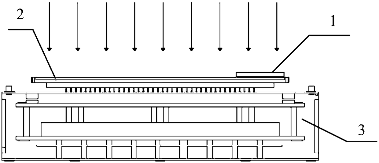
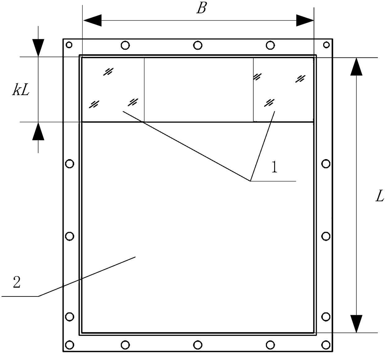
[0046] Such as figure 1 As shown, the present invention includes a filter component 1, an imaging component 2 and a calibration processing module 3.

[0047] The imaging component 2 is realized by an area array focal plane detector with a windowing function, and shares a detector with the remote sensor to be calibrated.

[0048] The filter component 1 filters out the light waves outside the spectral range of the calibration light source, and only passes the calibration light source that passes through the optical path system of the remote sensor to be calibrated; the filter component 1 can choose a narrow-band filter component or a filter film, and a narrow-band filter component Including the frame, the pressure ring and the filter, the filter is first installed in the frame, and then the filter is pressed with the pressure ring, and installed on the top of the imaging component 2 through the mounting hole reserved for the frame. If a filter film with filter function is used, it is...


PUM


Abstract

The invention provides an on-orbit calibration device and on-orbit calibration method for pointing precision of a remote sensor. The device includes a calibration processing module, a filter component, and an imaging component, wherein the filter component is mounted on the imaging component to filter out the light sources outside the range of a calibration source spectrum, and only enable a calibration light source passing through the optical path system of the remote sensor to be calibrated to pass through; the imaging area of the imaging component includes a calibration area and an imagingarea, the calibration area is located at the edge of the imaging area, the surface of the calibration area is installed with the filter component, and the calibration area receives an optical signal of the calibration light source passing through the filter component, converts the optical signal into an electrical signal, and outputs the electrical signal to the calibration processing module; theimaging area receives the optical signal of an observation target, converts the optical signal of the observation target into an electrical signal, and outputs the electrical signal to an external digital transmission subsystem; and the calibration processing module determines the position coordinate of the calibration light source on the imaging component according to the electrical signal of thecalibration light source, and completes the on-orbit calibration of the pointing accuracy of the remote sensor. The on-orbit calibration device and on-orbit calibration method for pointing precisionof the remote sensor have the advantages of compact structure, convenient installation and high reliability.

Description

Technical field [0001] The invention relates to a remote sensor pointing accuracy on-orbit calibration device and method, belonging to the technical field of on-orbit calibration. Background technique [0002] In the existing calibration light source receiving device on the medium and large linear array cameras: at both ends of the focal plane assembly of the camera linear array detector, a heavy kilogram-level area array detector focal plane assembly needs to be separately provided. If the existing calibration light source receiving device is directly applied to the area array micro-nano remote sensor within 30kg, the weight burden of several kilograms will cause the overweight pressure of the micro-nano remote sensor and increase the focal surface volume of the micro-nano remote sensor. Affect the adaptability of the remote sensor platform carried by the micro-nano remote sensor. At the same time, additional area array light source receivers are added at both ends of the linea...

Claims


Application Information

Patent Timeline
Patent Type & Authority Applications(China)
IPC IPC(8): G01M11/02
CPCG01M11/0221
Inventor 吴俊于艳波朱忠尧李娜康少英杨沐夏中秋赵野张孝弘
Owner BEIJING RES INST OF SPATIAL MECHANICAL & ELECTRICAL TECH
Why Eureka
Try Eureka