
Floor wax detection device

A testing equipment, floor wax technology, applied in the direction of measuring devices, testing wear resistance, instruments, etc., can solve the problems of mold, matte loss, low hardness of wooden floors, etc., to achieve high detection accuracy, controllable detection process, simple structure

Pending Publication Date: 2018-12-18
ZHEJIANG NEW INSIGHT MATERIAL TECH CO LTD
View PDF0 Cites 0 Cited by
  • Summary
  • Abstract
  • Description
  • Claims
  • Application Information

AI Technical Summary

Problems solved by technology

Wooden floor is loved by consumers because of its natural beauty, no pollution, easy processing, and good thermal insulation. However, wooden floor has defects such as low hardness, poor corrosion resistance, and easy insects.
If you do not pay attention to the maintenance of the wooden floor, it is easy to be worn, even moldy or matte.

Method used


Image

  • Floor wax detection device

Examples


Embodiment 1

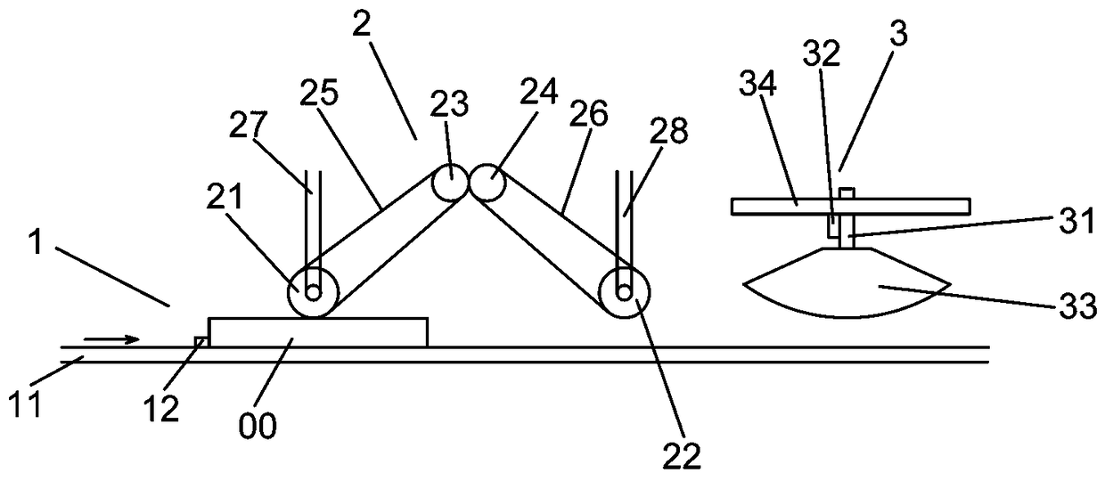
[0025] Example one: such as figure 1 Shown is only one of the embodiments of the present invention. A floor wax detection device includes a conveyor 1, a pressing device 2 and an induction device 3. The conveyor 1 includes a conveyor belt 11 and is arranged on the conveyor belt 11 The limit block 12, the squeezing device 2 includes a first squeeze roller 21, a second squeeze roller 22, a first drive roller 23 and a second drive roller 24, the first squeeze roller 21 passes through the first The traction belt 25 is connected to the first drive roller 23, and the second squeeze roller 22 is connected to the second drive roller 24 through a second belt 26, the first drive roller 23 and the second drive roller 24 In engagement with each other, the sensing device 3 includes a movable plate 31 and a fixed plate 32, the end of the movable plate 31 is provided with an induction head 33, and the fixed plate 32 is electrically connected with a circuit board 34.

[0026] In order to test t...

Embodiment 2

[0031] Example two, still as figure 1 As shown, it is still one of the embodiments of the present invention. In order to make the floor wax detection equipment of the present invention more practical and stable, with high detection accuracy, the present invention also has the following designs:

[0032] First add on the conveyor 1:

[0033] Since the floor to be tested 00 will be subjected to friction in two opposite directions, in order to better facilitate the transmission of the floor to be tested 00, at least one limit block 12 must be set at the front and the rear of the transmission direction of the floor to be tested 00. In addition, a plurality of floors 00 to be tested can be simultaneously conveyed on the conveyor belt 11 to perform a simulated squeeze friction test in turn, so there are at least multiple sets of limit blocks 12, so the number of limit blocks 12 is at least one.

[0034] Then the addition of squeeze device 2:

[0035] In order to better simulate the scratch...


PUM

PropertyMeasurementUnit
Angleaaaaaaaaaa

Abstract

The invention provides a floor wax detection device, and relates to the technical field of floors. The floor wax detection device comprises a conveying device, an extruding device and an induction device; the conveying device comprises a conveying belt and a limiting block arranged on the conveying belt; the extruding device comprises a first extruding roller, a second extruding roller, a first driving roller and a second driving roller; the first extruding roller is connected with the first driving roller through a first traction belt; the second extruding roller is connected with the seconddriving roller through a second belt; the first driving roller and the second driving roller are meshed with each other; the induction device comprises a movable plate and a fixed plate; an inductionhead is arranged at the end part of the movable plate; and the fixed plate is electrically connected with a circuit board. The floor wax detection device is simple in structure, safe and stable; the two-way abrasion detection can be performed, and the detection precision is high; and the detection process can be controlled.

Description

Technical field [0001] The invention relates to the technical field of flooring, [0002] In particular, the present invention relates to a floor wax detection device. Background technique [0003] With the improvement of people's quality of life, there are higher requirements for aesthetics and comfort. Now some homes, outdoor floors and platforms will be laid with wooden floors to increase aesthetics. [0004] Floor decoration is an indispensable part of home decoration. Using wooden floor to decorate home can make the room look elegant. With the improvement of people's living standards and the continuous improvement of the living environment, more and more families choose wood flooring for decoration. Wood flooring is favored by consumers because of its beauty, natural appearance, no pollution, easy processing, and good heat preservation. However, wood flooring has defects such as low hardness, poor corrosion resistance, and easy insects. If you do not pay attention to the main...

Claims


Application Information

Patent Timeline
IPC IPC(8): G01N3/56
CPCG01N3/56G01N2203/0019G01N2203/005
Inventor 陈惠文金国伟顾义杰
Owner ZHEJIANG NEW INSIGHT MATERIAL TECH CO LTD
Features
  • Generate Ideas
  • Intellectual Property
  • Life Sciences
  • Materials
  • Tech Scout
  • Unparalleled Data Quality
  • Higher Quality Content
  • 60% Fewer Hallucinations
Learn More