Power electronic equipment monitoring and diagnosing system and method

A technology of power electronics and diagnostic systems, applied in the direction of measuring electricity, measuring devices, measuring electrical variables, etc., can solve problems such as unavoidable economic losses, and achieve the effect of reducing economic losses and improving reliability

Active Publication Date: 2018-12-18
SHANGHAI UNIV
View PDF7 Cites 2 Cited by
  • Summary
  • Abstract
  • Description
  • Claims
  • Application Information

AI Technical Summary

Problems solved by technology

[0003] At present, the monitoring and fault diagnosis of power electronic equipment is mainly to give an alarm to the time when the fault occurs, and the resulting economic loss is unavoidable, so it is only possible to improve the power electronic equipment and analyze the cause of the fault

Method used


Image

  • Power electronic equipment monitoring and diagnosing system and method
  • Power electronic equipment monitoring and diagnosing system and method

Examples


Embodiment Construction

[0034] Specific embodiments of the present invention will be further described below in conjunction with the accompanying drawings.

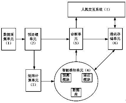
[0035] Such as figure 1 As shown, a power electronic equipment monitoring and diagnosis system includes a data acquisition unit 1, a preprocessing unit 2, a matrix calculation unit 3, an intelligent perception unit 4, a diagnosis unit 5, a communication storage unit 6, and a human-computer interaction system 7; The data acquisition unit 1 is connected to the preprocessing unit 2, the preprocessing unit 2 is connected to the matrix calculation unit 3 and the diagnosis unit 5, the matrix calculation unit 3 is connected to the intelligent sensing unit 4, the intelligent sensing unit 4 is connected to the diagnosis unit 5, and the communication storage unit 6 The diagnostic unit 5 is connected to the communication storage unit 6 and the human-computer interaction system 7 , and the communication storage unit 6 is connected to the human-computer inte...


PUM


Abstract

The invention discloses a power electronic equipment monitoring and diagnosing system and method thereof. The system comprises a data collecting unit, a preprocessing unit, a matrix calculating unit,an intelligent sensing unit, a diagnosing unit, a communication storage unit and a man-machine interaction system. The method comprises the steps of: performing simple processing on collected data, and obtaining a state component of model through matrix calculation so as to establish a system model; performing rapid and large time scale simulation on input signal to obtain a given output; and processing the given output and the actual output to obtain a system prediction component, and finally obtaining a device diagnosing result. According to the power electronic equipment monitoring and diagnosing system and method thereof, the running state of the power electronic equipment can be predicted before the power electronic equipment fails; the situation of the power electronic equipment canbe accurately diagnosed in time; economic loss and threats to personnel caused by failure of the power electronic equipment can be reduced; and the reliability of the power electronic equipment is improved.

Description

technical field [0001] The invention relates to the field of power electronic equipment, in particular to a monitoring and diagnosis system and method for power electronic equipment. Background technique [0002] In recent years, power electronic equipment has developed rapidly and has been used in rail traction, aerospace, electric vehicles, power systems, new energy power generation, energy storage systems and other fields. With the application of power electronic equipment, accidents caused by the failure of power electronic equipment occur frequently, which brings a series of economic losses and threatens the safety of personnel. Therefore, more and more attention has been paid to the monitoring of power electronic equipment. [0003] At present, the monitoring and fault diagnosis of power electronic equipment is mainly to give an alarm when the fault occurs, and the economic loss caused by it is inevitable. Only the power electronic equipment can be improved and the ca...

Claims


Application Information

Patent Timeline
Patent Type & Authority Applications(China)
IPC IPC(8): G01R31/00
CPCG01R31/00
Inventor 汪飞罗雨陆思远舒心怡全晓庆吴春华
Owner SHANGHAI UNIV
Why Eureka
Try Eureka