
Multi-cascaded distributed microscopic CT imaging system

A CT imaging, distributed technology, applied in the direction of using nuclear magnetic resonance imaging system for measurement, magnetic resonance measurement, magnetic variable measurement, etc., can solve the problems of low conversion efficiency and waste of visible light, and achieve high time resolution and high signal quality Effects of Noise Ratio, High Spatial Resolution

Pending Publication Date: 2018-12-18
CAPITAL NORMAL UNIVERSITY
View PDF0 Cites 4 Cited by
  • Summary
  • Abstract
  • Description
  • Claims
  • Application Information

AI Technical Summary

Problems solved by technology

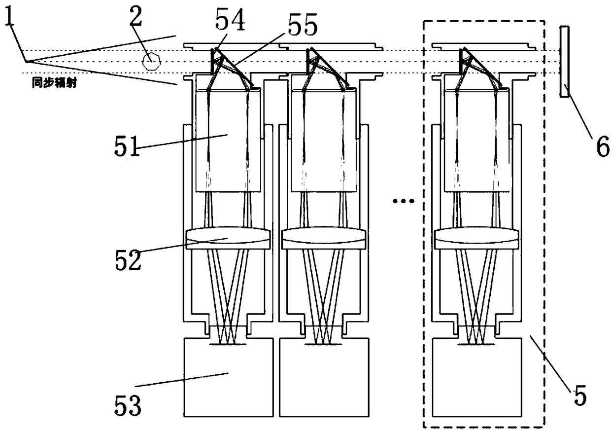
This method can achieve high-resolution X-ray imaging through the optical amplification of the microscopic objective lens 51, but the traditional micro-CT system based on an optical coupler and a visible light detector can only complete one X-ray-visible light conversion.
Restricted by the small depth of field of the microscope objective lens 51 (several microns), the scintillator 54 is usually very thin, which results in low conversion efficiency of X-rays passing through the scintillator 54 to visible light, and most of the X-rays directly penetrate the scintillator 54 being wasted

Method used


Image

  • Multi-cascaded distributed microscopic CT imaging system
  • Multi-cascaded distributed microscopic CT imaging system
  • Multi-cascaded distributed microscopic CT imaging system

Examples


Embodiment Construction

[0022] In the drawings, the same or similar reference numerals are used to denote the same or similar elements or elements having the same or similar functions. Embodiments of the present invention will be described in detail below in conjunction with the accompanying drawings.

[0023] In the description of the present invention, the terms "central", "longitudinal", "transverse", "front", "rear", "left", "right", "vertical", "horizontal", "top", " The orientation or positional relationship indicated by "bottom", "inner", "outer", etc. is based on the orientation or positional relationship shown in the drawings, and is only for the convenience of describing the present invention and simplifying the description, rather than indicating or implying the referred device or element Must have a specific orientation, be constructed and operate in a specific orientation, and therefore should not be construed as limiting the scope of the invention.

[0024] Such as figure 1 and as f...


PUM


Abstract

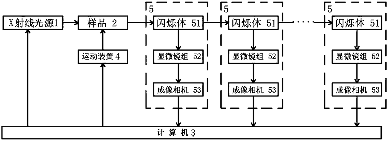
The invention discloses a multi-cascaded distributed microscopic CT imaging system comprising an X-ray light source and microscopic CT imaging modules; each microscopic CT imaging module comprises a microobjective, a tube lens, an imaging camera and a scintillator; the X-ray light source is arranged on one side of a sample; the scintillators of the microscopic CT imaging modules are sequentially arranged on the straightline propagation light path of X rays emitted by the X-ray light source after passing through the sample according to a sequential order; the microobjective, the tube lens and the imaging camera are sequentially positioned on the light path of visible light emitted by the scintillator; and the imaging camera collects the image of the sample at each position. According to thesystem provided by the invention, multiple times of X-ray-visible light conversion can be achieve, the emission energy of the X rays can be fully converted and separately imaged on the image detection plane of the imaging camera of each level of microscopic CT imaging module, a multi-image cross-scale synthesis technology is used, and finally, the images with high spatial resolution, high time resolution and high signal-noise ratio are acquired, and the imaging efficiency is significantly enhanced.

Description

technical field [0001] The invention relates to the technical field of micro-imaging, in particular to a multi-cascade distributed micro-CT imaging system. Background technique [0002] The micro-CT system based on optocoupler and visible light detector is currently the world's leading high-resolution X-ray imaging technology. The basic principle is to use the scintillator 54 to convert X-rays into visible light, and then use the microscope objective lens 51 group to amplify the visible light distribution and image it on the camera chip. In this method, high-resolution X-ray imaging can be realized through the optical amplification of the microscope objective lens 51 . However, traditional micro-CT systems based on optical couplers and visible light detectors usually only complete one X-ray-visible light conversion. Restricted by the small depth of field of the microscope objective lens 51 (several microns), the scintillator 54 is usually very thin, which results in low con...

Claims


Application Information

Patent Timeline
Patent Type & Authority Applications(China)
IPC IPC(8): G01R33/48
CPCG01R33/48
Inventor 张慧滔朱溢佞张朋毛珩
Owner CAPITAL NORMAL UNIVERSITY
Learn More