Unlock instant, AI-driven research and patent intelligence for your innovation.

Motion Error Compensation Method for 3D Imaging of Heavy Navigation Array Synthetic Aperture Radar

A technology of three-dimensional imaging and array synthesis, which is applied in the direction of radio wave measurement systems and instruments, can solve problems such as array deformation error, difficulty in three-dimensional imaging, and influence on image inversion, so as to increase volume, weight and power consumption, and facilitate engineering realization Effect

Active Publication Date: 2022-08-02
INST OF ELECTRONICS CHINESE ACAD OF SCI
View PDF0 Cites 0 Cited by
  • Summary
  • Abstract
  • Description
  • Claims
  • Application Information

AI Technical Summary

Problems solved by technology

In practice, the array SAR based on heavy navigation oversampling realizes three-dimensional imaging through multiple passes of the same scene at different times. The relative positions between the phase centers in the interior will also change, seriously affecting the image inversion (see Salzman J., Akamine D., Lefevre R., et al.Interrupted synthetic aperture radar(SAR)[J].IEEE Aerospace and Electronic Systems Magazine,2002,17(5):33-39)
[0003] In view of the above background, relevant researchers have worked on array error correction, platform motion error compensation, and multi-pass echo data registration (see Yang Zemin, Sun Guangcai, Xing Mengdao, etc. Airborne 3D SAR motion compensation based on multi-channel joint self-focusing technology[ J]. The Journal of Electronics and Information Technology, 2012, 34(7): 1581-1588) and other aspects have done corresponding research work, but the research on the down-looking 3D imaging and motion error compensation of heavy-flying array SAR under the condition of motion error is relatively limited. few
Due to the heavy flight of the airborne array antenna SAR, on the one hand, there is an array deformation error, and on the other hand, there is a track curve offset, which brings many difficulties to its three-dimensional imaging.

Method used


Image

  • Motion Error Compensation Method for 3D Imaging of Heavy Navigation Array Synthetic Aperture Radar
  • Motion Error Compensation Method for 3D Imaging of Heavy Navigation Array Synthetic Aperture Radar
  • Motion Error Compensation Method for 3D Imaging of Heavy Navigation Array Synthetic Aperture Radar

Examples


Embodiment Construction

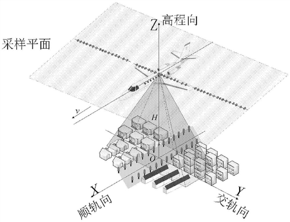
[0059] In order to make the objectives, technical solutions and advantages of the present disclosure clearer, the present disclosure will be further described in detail below with reference to the specific embodiments and the accompanying drawings.

[0060] It should be noted that, in the drawings or descriptions in the specification, the same drawing numbers are used for similar or identical parts. Implementations not shown or described in the drawings are forms known to those of ordinary skill in the art. Additionally, although examples of parameters including specific values ​​may be provided herein, it should be understood that the parameters need not be exactly equal to the corresponding values, but may be approximated within acceptable error tolerances or design constraints. Directional terms mentioned in the embodiments, such as "up", "down", "front", "rear", "left", "right", etc., only refer to the directions of the drawings. Accordingly, the directional terms used ar...


PUM


Abstract

The present disclosure provides a method for compensating three-dimensional imaging motion error of a heavy sailing array synthetic aperture radar, including: obtaining the position and array deformation measurement data of each subarray corresponding to each sailing pass, and performing polynomial fitting; Perform spatial modulation on echo data; use 3D BP imaging algorithm to obtain SAR 3D complex image pairs corresponding to each flight; perform interferometric processing on 3D complex images corresponding to MURA positive code; establish SAR echo signal-interferometric complex image frequency domain The relationship between the coefficient vectors, and solve the relationship between each flight; inversely transform the obtained frequency domain coefficient vector to the space domain, equivalently realize the array deformation error compensation and single flight 3D imaging; return the positive code to MURA The phase compensation is performed on the single-passage complex image formed by the wave; the coherent accumulation of each complex image after compensation is performed to realize the three-dimensional imaging of the heavy-passover array SAR. The disclosed method is of great significance to the application of airborne / spaceborne heavy duty voyage observation data.

Description

technical field [0001] The present disclosure relates to the field of radar imaging processing, and in particular, to a three-dimensional imaging motion error compensation method for heavy-navigation through-array synthetic aperture radar. Background technique [0002] The array antenna SAR realizes the three-dimensional resolution of the observation scene by forming a two-dimensional synthetic aperture array and a broadband signal in the wave propagation direction in the sampling space, where the resolution of the array direction is limited by the length of the array in the cross-orbit direction. Re-navigation oversampling in the array direction can expand the equivalent array length to improve the cross-orbit resolution (see Li Daojing, Teng Xiumin. Cross-Track Sparse Flight Simulation Analysis for Airborne Sparse Array Downward-Looking 3D Imaging Radar [C]. in Geoscience and Remote Sensing Symposium (IGARSS), Canada, July 2011:1686-1688). Under the ideal oversampling con...

Claims


Application Information

Patent Timeline
Patent Type & Authority Patents(China)
IPC IPC(8): G01S7/40
CPCG01S7/4052
Inventor 田鹤李道京
Owner INST OF ELECTRONICS CHINESE ACAD OF SCI