T/R component control and monitoring method based on ARM and FPGA architectures
A component and architecture technology, applied in the direction of program control, computer control, general control system, etc., can solve problems such as equipment failure monitoring paralysis, increase system complexity, etc., to ensure stable and safe work, save labor costs and time costs, The effect of improving reliability
- Summary
- Abstract
- Description
- Claims
- Application Information
AI Technical Summary
Problems solved by technology
Method used
Image

Examples
Embodiment Construction
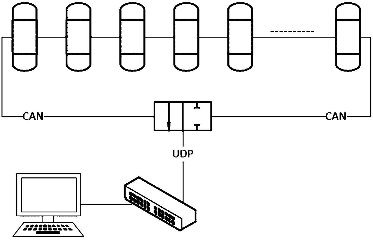
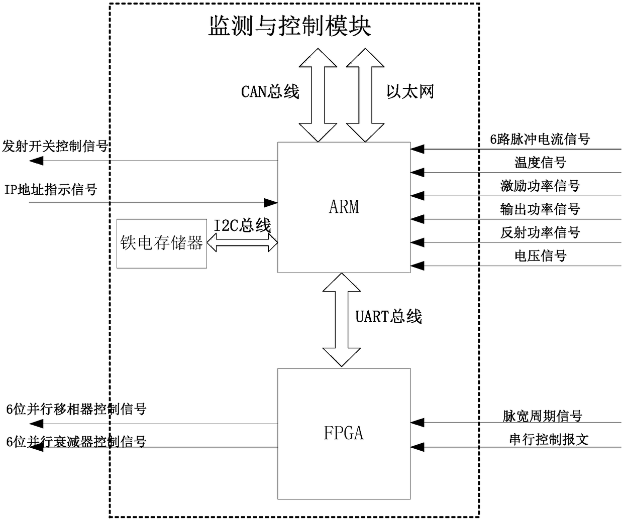
[0010] The main control and processing unit adopts ARM architecture processor, and the T / R component adopts ARM+FPGA processor architecture. The main peripheral interfaces involved include GPIO, IIC, UART, CAN, Ethernet, and ADC. The real-time monitoring status indicators inside the T / R component include pulse current, temperature, excitation power, output power, reflected power, pulse voltage, pulse width period, and pulse width duty cycle. In this design, ARM chooses TM4C1294NCPDT chip, which is mainly responsible for monitoring status indicators and taking control and protection measures. The chip integrates rich peripheral interfaces to meet the needs of data communication and protection control in the system. The FPGA uses XC6SLX9-2CSG324I, which is mainly responsible for analyzing the pulse width period signal, obtaining the pulse width period and duty ratio index, and also responsible for completing beam control and STC control.
[0011] In the way of data interaction w...
PUM
 Abstract
Description
Claims
Application Information
 - R&D
- Intellectual Property
- Life Sciences
- Materials
- Tech Scout
- Unparalleled Data Quality
- Higher Quality Content
- 60% Fewer Hallucinations
Browse by: Latest US Patents, China's latest patents, Technical Efficacy Thesaurus, Application Domain, Technology Topic, Popular Technical Reports.
© 2025 PatSnap. All rights reserved.Legal|Privacy policy|Modern Slavery Act Transparency Statement|Sitemap|About US| Contact US: help@patsnap.com