Method and system for monitoring dangerous rock mass deformation by using synthetic aperture radar

A technology of synthetic aperture radar and dangerous rock mass, which is applied in radio wave measurement system, measurement device, radio wave reflection/re-radiation, etc. It can solve the problems of many noise points, more professional knowledge, and greater difficulty in technology promotion, etc. problems, to achieve the effect of ensuring reliability and high efficiency

Active Publication Date: 2018-12-18
中科卫星应用德清研究院 +3
View PDF6 Cites 8 Cited by
  • Summary
  • Abstract
  • Description
  • Claims
  • Application Information

AI Technical Summary

Problems solved by technology

Moreover, the monitoring work requires a lot of preliminary preparations, such as the deployment of nets and points. At the same time, the set monitoring points, such as benchmarking points and coordinate control points, are easily damaged by external man-made or natural
The points obtained by field measurement using traditional methods are usually isolated points, and the correlation bet

Method used


Image

  • Method and system for monitoring dangerous rock mass deformation by using synthetic aperture radar
  • Method and system for monitoring dangerous rock mass deformation by using synthetic aperture radar
  • Method and system for monitoring dangerous rock mass deformation by using synthetic aperture radar

Examples


Example Embodiment

[0059] Example 1

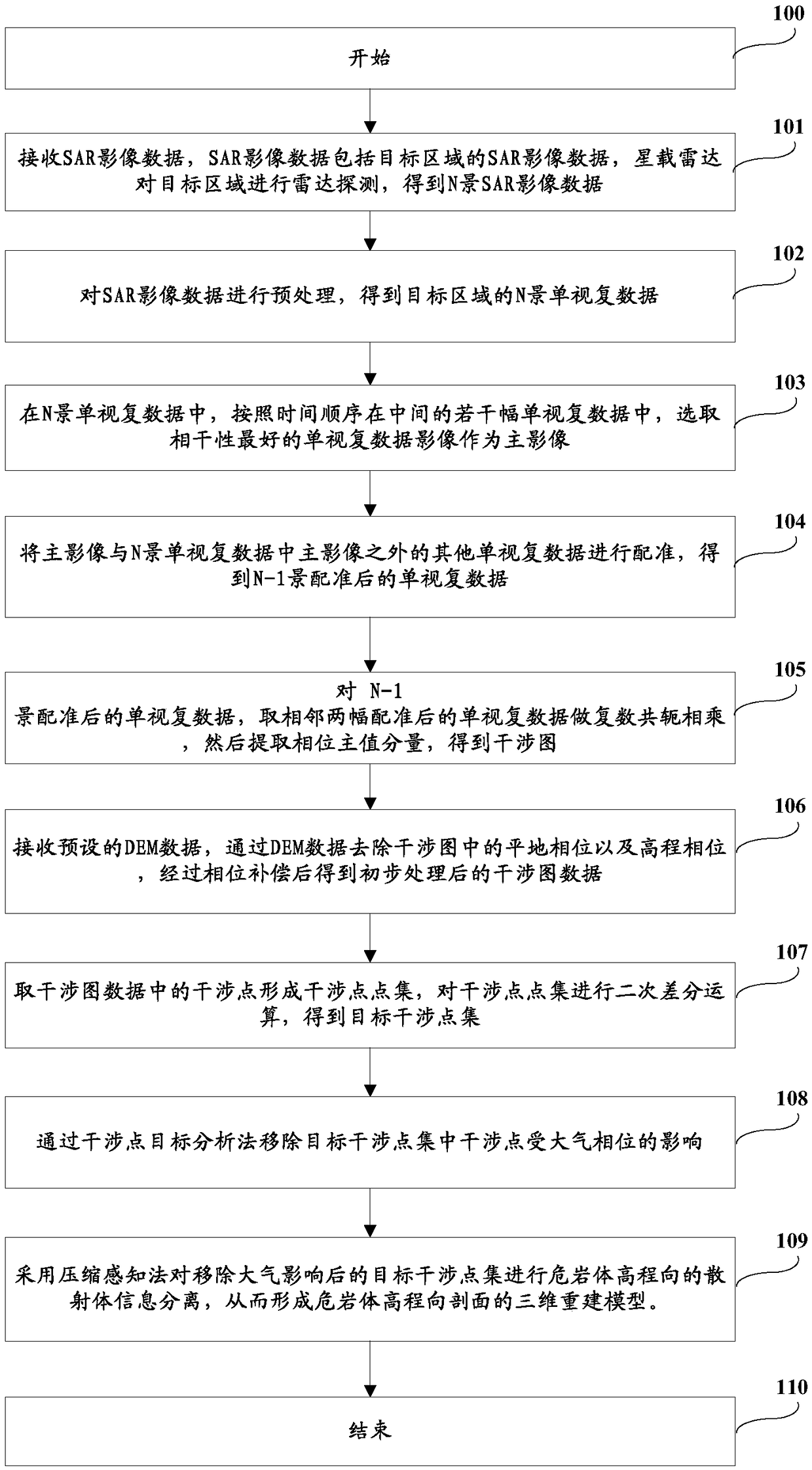
[0060] Such as figure 1 Shown is a flow chart of a method for monitoring the deformation of a dangerous rock mass by synthetic aperture radar according to an embodiment of the present invention, which includes the following steps:

[0061] Step 100: Start.

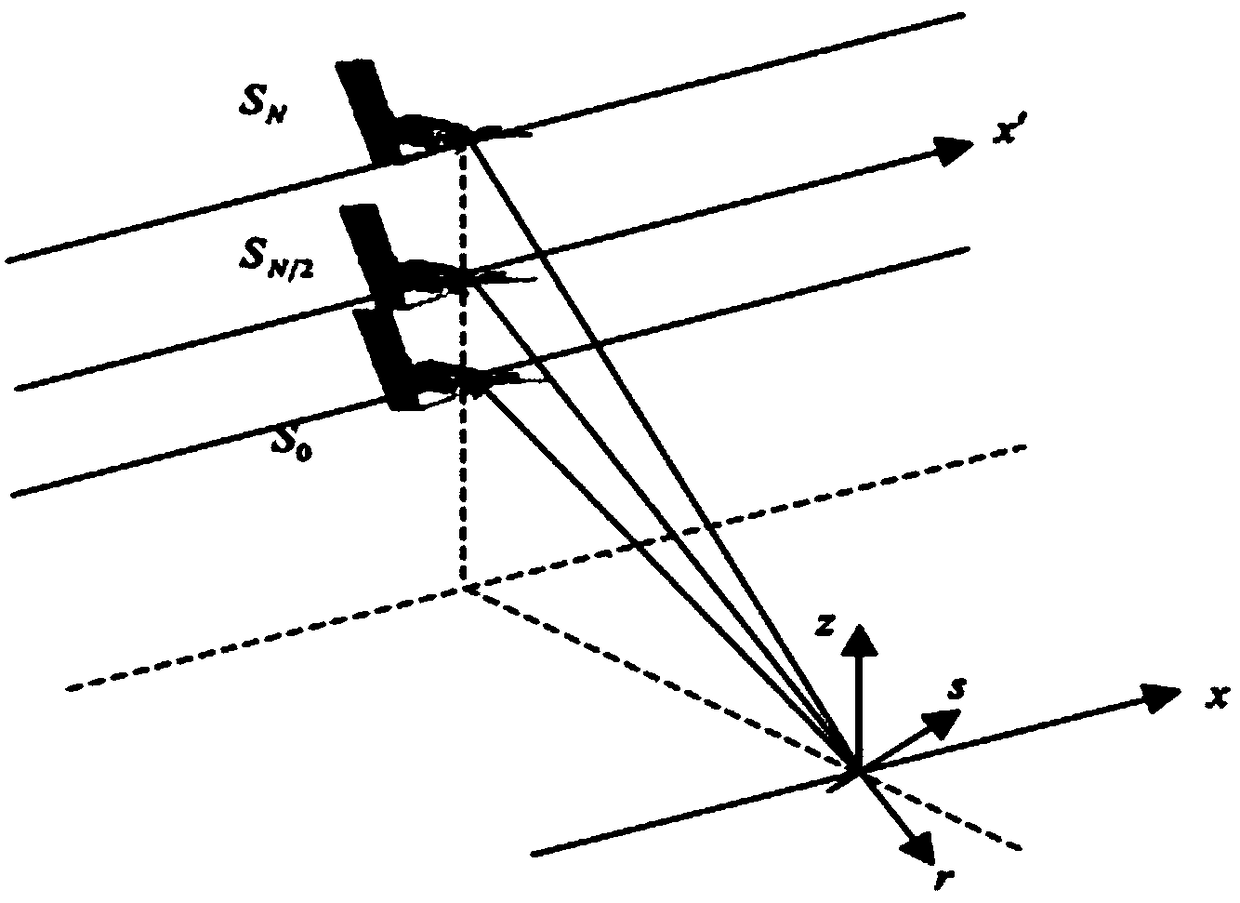
[0062] Step 101: Receive SAR image data, where the SAR image data includes SAR image data of a target area, and the spaceborne radar performs radar detection on the target area to obtain the SAR image data of N scenes.

[0063] It should be noted that a SAR (Synthetic Aperture Radar) image, or SLC, is an image composed of multiple pixels. Each pixel represents a ground resolution unit and contains the above-mentioned phase and backscatter intensity information of the ground object.

[0064] Step 102: Perform preprocessing on the SAR image data to obtain N scene single-view complex data of the target area.

[0065] Step 103: Among the single-view complex data of N scenes, select the single-view complex data image w...

Example Embodiment

[0116] Example 2

[0117] Step 200: Start.

[0118] Step 201: Receive SAR image data, the SAR image data includes the SAR image data of the target area, and the spaceborne radar performs radar detection on the target area to obtain the SAR image data of the N scene.

[0119] Step 202: Perform preprocessing on the SAR image data to obtain N scene single-view complex data of the target area.

[0120] Step 203: Among the single-view complex data of N scenes, among the plurality of middle single-view complex data in chronological order, select the single-view complex data image with the best coherence as the main image.

[0121] Step 204: Register the main image with other single-view complex data other than the main image in the single-view complex data of N scenes to obtain registered single-view complex data of N-1 scenes.

[0122] Step 205: For the registered single-view complex data of the N-1 scene, take two adjacent pieces of the registered single-view complex data to do the complex c...

Example Embodiment

[0130] Example 3

[0131] Step 300: Start.

[0132] Step 301: Receive SAR image data, the SAR image data includes the SAR image data of the target area, and the spaceborne radar performs radar detection on the target area to obtain the SAR image data of the N scene.

[0133] Step 302: Preprocessing the SAR image data to obtain N scenes of single-view complex data of the target area.

[0134] Step 303: Among the single-view complex data of N scenes, select the single-view complex data image with the best coherence as the main image from among several middle single-view complex data in chronological order.

[0135] Step 304: Register the main image with other single-view complex data other than the main image in the single-view complex data of N scenes to obtain registered single-view complex data of N-1 scenes.

[0136] Step 305: For the registered single-view complex data of the N-1 scene, take two adjacent pieces of the registered single-view complex data to do the complex conjugate mul...


PUM


Abstract

The invention discloses a method and a system for monitoring dangerous rock mass deformation by using synthetic aperture radar (SAR). The method comprises: receiving SAR image data; obtaining N-scenario single-view complex data according to the SAR image data; obtaining an interferogram according to the N-scenario single-view complex data; receiving preset DEM data to remove a flat ground phase and an elevation phase from the interferogram, and obtaining initially processed interferogram data after phase compensation; taking interference points in the interferogram data to form an interferencepoint set, performing a second differential operation on the interference point set to obtain a target interference point set; removing the interference points influenced by an atmospheric phase fromthe target interference point set by an interference point target analysis method; and separating scatterer information of dangerous rock mass elevation by compressed sensing on the target interference point set from which the atmospheric influence is removed, thus forming a three-dimensional reconstruction model of a dangerous rock mass elevation profile. The method and the system provide a basis for scientific analysis of dangerous rock mass collapse.

Description

technical field [0001] The invention relates to the technical field of digital photogrammetry of remote sensing images, and more specifically, to a synthetic aperture radar monitoring method and system for dangerous rock mass deformation. Background technique [0002] my country is a country prone to geological disasters, especially in the western region, where the geological environment is very complex. With the abnormal changes in the geological environment, the western region has become an area where geological disasters frequently occur. Dangerous rock collapses, landslides and mudslides are common geological disasters in the southwest region. Dangerous rock mass collapse is a global pan-generated mountain disaster. Its location is concealed, its instability and damage are sudden, and its disaster-causing consequences are catastrophic. It usually occurs on high and steep slopes and cliffs, posing a serious threat For the safety of mountain roads, towns and mines. [00...

Claims


Application Information

Patent Timeline
IPC IPC(8): G01S13/90
CPCG01S13/90G01S13/9023
Inventor 谢酬田帮森邵芸方昊然卞小林唐菲菲杨建国李明
Owner 中科卫星应用德清研究院
Why Eureka
Try Eureka