
Nano metal grating manufacturing method and nano metal grating

A technology of nano-metal and production method, which is applied in the production of nano-metal grating and the field of nano-metal grating, which can solve the problems of uneven display and the decline of the ability of the flat layer to block water and oxygen, and achieve the effect of avoiding the decline of ability

Inactive Publication Date: 2018-12-18
TCL CHINA STAR OPTOELECTRONICS TECH CO LTD
View PDF7 Cites 7 Cited by
  • Summary
  • Abstract
  • Description
  • Claims
  • Application Information

AI Technical Summary

Problems solved by technology

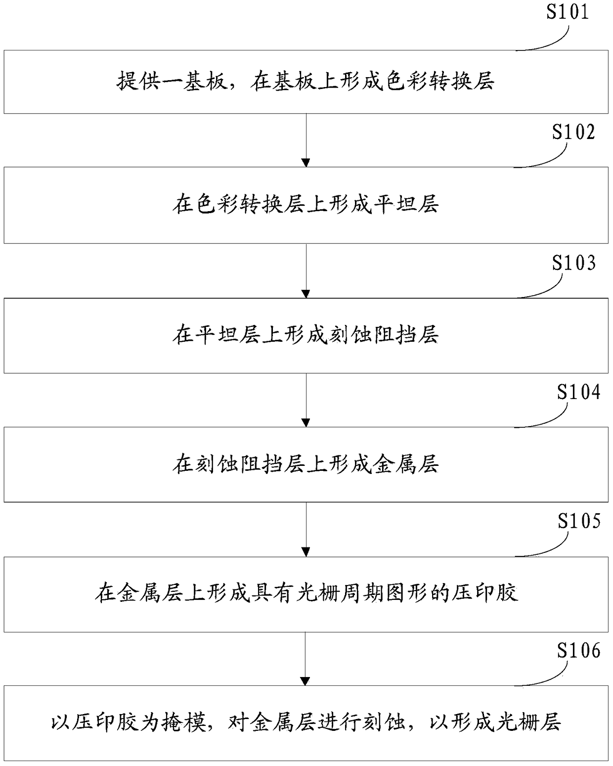
[0004] The main technical problem to be solved by the present invention is to provide a method for making a nano-metal grating and a nano-metal grating, which can avoid the problems of the flat layer being etched and the ability of the flat layer to block water and oxygen, and the display unevenness caused by optical diffraction.

Method used


Image

  • Nano metal grating manufacturing method and nano metal grating
  • Nano metal grating manufacturing method and nano metal grating
  • Nano metal grating manufacturing method and nano metal grating

Examples


Embodiment Construction

[0012] Certain words are used to refer to specific components in the description and claims, and those skilled in the art should understand that manufacturers may use different terms to refer to the same component. The specification and claims do not use the difference in name as a way to distinguish components, but use the difference in function of components as a basis for distinction. The present invention will be described in detail below in conjunction with the accompanying drawings and embodiments.

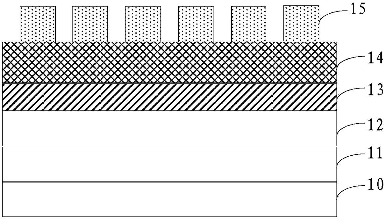
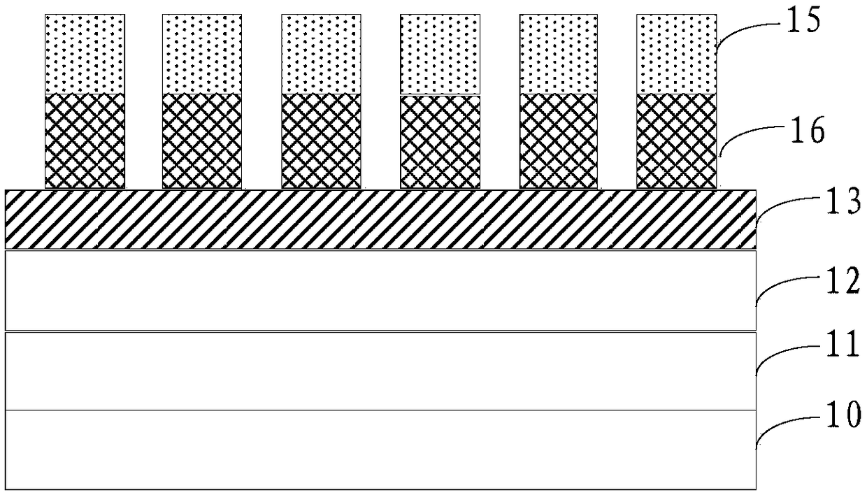
[0013] figure 1 It is a schematic flow chart of a method for fabricating a nanometer metal grating according to an embodiment of the present invention. Figure 2A-2B yes figure 1 Schematic diagram of the structure of the nanometer metal grating during the fabrication process of the fabrication method shown. It should be noted that if there are substantially the same results, the method of the present invention does not figure 1 The flow sequence shown is limited. Such a...


PUM

PropertyMeasurementUnit
thicknessaaaaaaaaaa
thicknessaaaaaaaaaa
thicknessaaaaaaaaaa

Abstract

The invention discloses a nano metal grating manufacturing method and a nano metal grating. The method comprises the following steps: providing a substrate, and forming a flat layer on the substrate;forming an etching barrier layer on the flat layer; forming a metal layer on the etching barrier layer; forming an embossed rubber comprising grating periodic pattern on the metal layer; taking the embossed rubber as a mask, etching a metal layer, thereby forming the grating layer. By the mode above, a problem of decline in ability of obstructing water oxygen of the flat layer caused by etching for the flat layer and a problem of uneven display caused by optical diffraction are avoided.

Description

technical field [0001] The invention relates to the technical field of liquid crystal display, in particular to a method for manufacturing a nanometer metal grating and the nanometer metal grating. Background technique [0002] Nano-metal gratings can transmit incident light whose electric field direction is perpendicular to the direction of the grating, and reflect light whose electric field direction is parallel to the direction of the grating. Based on this working principle, the reflected light can be reused by adding an anti-reflection film, etc. , so the ability of the nano metal grating as a display polarizer to transmit incident light is far greater than that of the traditional polarizer, the transmittance can reach more than 90%, and the contrast ratio is also as high as 10000:1, which can greatly improve the transmittance of the LCD Ratio and contrast, to meet the needs of high penetration and high contrast in the market. [0003] At present, in the process of mak...

Claims


Application Information

Patent Timeline
Patent Type & Authority Applications(China)
IPC IPC(8): G02B5/30G02B5/18G02F1/1335G03F7/00
CPCG02B5/1857G02B5/3058G02F1/133528G03F7/0002G02F1/133548
Inventor 侯俊陈书志
Owner TCL CHINA STAR OPTOELECTRONICS TECH CO LTD
Learn More