A battery module for carrying out overcurrent by lamination

A battery module and overcurrent technology, which is applied to battery components, circuits, electrical components, etc., can solve the problems of copper row temperature rise, current loss, and overcurrent distance, etc., to solve the problem of excessive temperature rise, Improve productivity and improve reliability

Pending Publication Date: 2018-12-18
FUJIAN YIDONGLI ELECTRONICS TECH CO LTD
View PDF0 Cites 1 Cited by
  • Summary
  • Abstract
  • Description
  • Claims
  • Application Information

AI Technical Summary

Problems solved by technology

[0004] 1. The copper bars of each module are fixed by bolts, and the process is relatively cumbersome, and when the number of bolts is too large, the reliability of the entire battery system is reduced; and the number of copper bars is large, and the cost is high
[0005] 2. The busbar is currently formed by laser welding of copper sheets and nickel sheets. The material cost of this structure is relatively high
However, in the actual application of the whole vehicle, it may lead to high current discharge, and the duration is long, which may easily lead to a high temperature rise of the copper bar, increase the internal heat generation source of the battery pack, and cause the battery system temperature rise to be too high and affect the use
[0007] 4. The design of this structure has a large path of overcurrent, which may cause the loss of current during overcurrent

Method used


Image

  • A battery module for carrying out overcurrent by lamination
  • A battery module for carrying out overcurrent by lamination
  • A battery module for carrying out overcurrent by lamination

Examples


Embodiment Construction

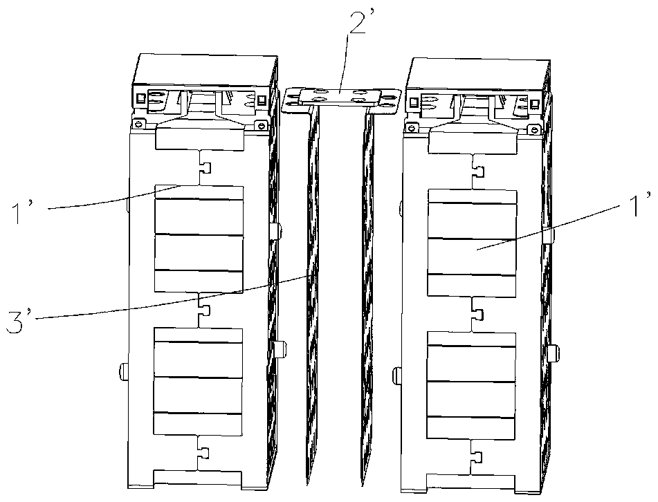
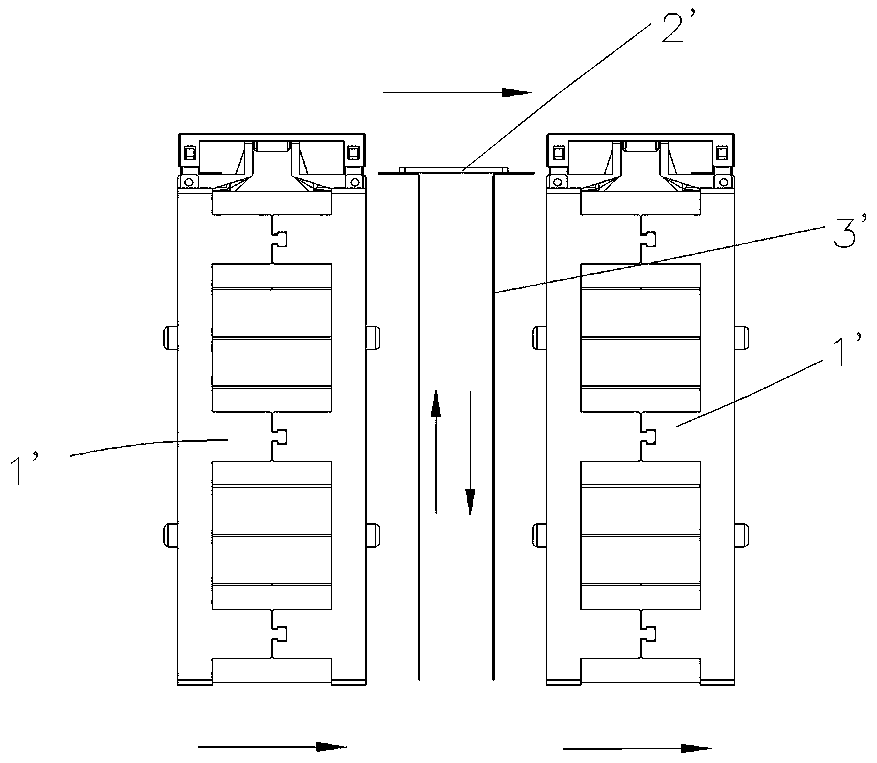
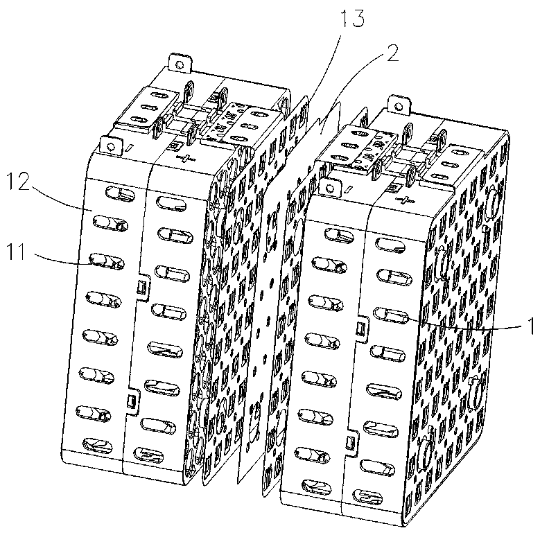
[0020] Such as Figure 3 to Figure 5 As shown, a battery module for overcurrent through pressing includes a plurality of battery modules 1 , a plurality of intermediate copper or aluminum sheets 2 , a plurality of long screws 3 , and two end plates 4 .

[0021] A plurality of battery modules 1 are arranged side by side, a middle copper sheet or aluminum sheet 2 is arranged between every two adjacent battery modules 1, and the two battery modules 1 arranged at the outermost end are respectively provided with an end plate 4, through a plurality of The long screw 3 connects the plurality of battery modules 1 , the plurality of intermediate copper or aluminum sheets 2 , and the end plates 4 to form a battery module.

[0022] The battery module 1 includes a cell 11, a bracket 12, and a nickel sheet 13; the cell 11 is arranged in the bracket 12; the cell 11 and the bracket 12 are welded to the nickel sheet 13 by resistance .

[0023] Description of working process:

[0024] The b...


PUM


Abstract

The invention relates to a battery module for carrying out overcurrent by pressing, comprising a plurality of battery modules, a plurality of intermediate copper or aluminum sheets, a plurality of long screws and two end plates; The plurality of battery modules are arranged side by side, one intermediate copper sheet or aluminum sheet is arranged between each adjacent battery module, two battery modules arranged at the outermost end are respectively provided with one end plate, and the plurality of battery modules, the plurality of intermediate copper sheets or aluminum sheets and the two endplates are connected through the plurality of long screws to form a battery module. Further, the battery module comprises a battery cell, a bracket and a nickel sheet; The battery cell is arranged inthe bracket; The battery cell and the bracket are electrically welded with the nickel sheet. The invention reduces the cost of the battery system and the types of materials used. Reduce bolt-on structure, provide productivity, and improve reliability of battery systems; The problem that the temperature rise is too high due to the difference between overcurrent design and actual operation conditions is solved.

Description

technical field [0001] The invention relates to the technical field of batteries, in particular to a battery module for carrying out overcurrent through pressing. Background technique [0002] With the development of new energy electric vehicles, the requirements for the capacity, volume, cell combination, heat dissipation and fixation of the battery box are getting higher and higher. There must be a more reasonable structure, higher composition density, reasonable structure, and reliable battery installation. modules to meet the requirements of battery box safety performance. [0003] The structure of the traditional battery module is as follows figure 1 and figure 2 As shown, the upper ends of two adjacent battery modules 1' are connected by a copper bar 2', a busbar (copper sheet + nickel sheet) 3' is arranged in the middle, and the two battery modules are assembled with end plates through long screws. The way of overcurrent is to lead to the upper copper bar 2' throu...

Claims


Application Information

Patent Timeline
Patent Type & Authority Applications(China)
IPC IPC(8): H01M2/20H01M50/502H01M50/503H01M50/522
CPCH01M50/502Y02E60/10
Inventor 曾庆磊邓长水戴佳伟张建明陈晓济
Owner FUJIAN YIDONGLI ELECTRONICS TECH CO LTD
Why Eureka
Try Eureka