A nodal grounding electrode

A technology of grounding body and grounding conductor, which is applied in the direction of connecting contact materials to achieve the effect of saving manpower and cost and simple structure

Pending Publication Date: 2018-12-18
武汉中洋博宇科技发展有限公司
View PDF3 Cites 0 Cited by
  • Summary
  • Abstract
  • Description
  • Claims
  • Application Information

AI Technical Summary

Problems solved by technology

[0004] The purpose of the present invention is to provide a jointed grounding body to solve the above-mentioned shortcomings in the existing grounding grid

Method used


Image

  • A nodal grounding electrode

Examples


Embodiment 1

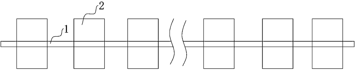
[0026] Such as figure 1 As shown, the present invention provides a hub-type grounding body, which includes a ground conductor 1 for laying in a pre-buried trench and a plurality of ground hubs 2 distributed along the length direction of the ground conductor 1 . The grounding conductor 1 includes an inner core and an anti-corrosion layer covering the outside of the inner core, wherein at least one inner core is provided, and each inner core is composed of single or multiple conductive wires, and the specific conductive wires are various conductive metals or Composite conductors composed of conductive metals can also be conductive graphite or conductors made of graphite and other non-metallic conductors. The structure of the inner core is covered by an anti-corrosion layer to avoid the grounding conductor 1 being easily damaged due to being buried underground for a long time. In case of corrosion, ensure the safety protection of the grounding body.

[0027] As mentioned above, ...

Embodiment 2

[0029] The difference from Embodiment 1 is that the grounding conductor 1 is laid vertically underground, so that multiple grounding hubs 2 are distributed vertically underground, that is, in places with high soil resistivity, when the buildable area is constant, only the A vertical trench is opened underground along the direction perpendicular to the ground, and the grounding joints 2 are vertically distributed in the trench. Even if the grounding resistance is effectively reduced, large-scale excavation of soil is not required, which effectively saves manpower and cost.

[0030] The jointed grounding body of the present invention utilizes one or more grounding conductors 1 to connect multiple grounding joints 2 to form a jointed grounding grid. The joints 2 are distributed in the trench, so that each grounding joint 2 can be in close contact with the soil in all directions and act independently, reducing the contact resistance between a single grounding joint 2 and the surrou...


PUM


Abstract

A nodal grounding electrode includes a ground conductor for laying in a pre-buried trench and a plurality of ground headers distributed along a length direction of the ground conductor, the groundingcollector section is a conductor with a regular polyhedron structure, and each ground header is connected to the ground conductor and forms a separate node for reducing ground resistance, Grounding conductors are connected to a plurality of independent nodes to form a multi-node grounding grid for continuous scattering of lightning energy and its release into the earth, The hub-and-spoke groundingelectrode of the invention connects a plurality of grounding hub-and-spoke to form a hub-and-spoke grounding grid by using one or more grounding conductors, Each grounding joint can act independentlyand reduce the contact resistance between the grounding electrode and the surrounding earth medium, which is convenient for the grounding electrode to continuously reduce the surrounding earth resistance, and the lightning energy is continuously dispersed and safely released into the earth when flowing through the grounding electrode, without excavating the soil in a large area, thus saving manpower and cost.

Description

technical field [0001] The invention relates to the technical field of lightning protection and grounding of electric power systems, in particular to a joint-type grounding body. Background technique [0002] The grounding device of the transmission line is the basic guarantee and important measure to maintain the safe and reliable operation of the power system and ensure the safety of electrical equipment and operating personnel. The underground plays the role of lightning protection, providing effective protection for transmission lines, so as to avoid power outages caused by lightning strikes, which is of great significance to the safe operation of the power system and the reliability of power supply. [0003] In the existing grounding devices, the grounding grid is the key link related to the success of lightning protection. However, in places with high soil resistivity, the area of ​​the grounding grid must be large. In order to meet the requirements of grounding resist...

Claims


Application Information

Patent Timeline
Patent Type & Authority Applications(China)
IPC IPC(8): H01R4/66
CPCH01R4/66
Inventor 史向平侯波房灵光汪绍华
Owner 武汉中洋博宇科技发展有限公司
Why Eureka
Try Eureka