Compensation circuit for overcurrent protection
A compensation circuit and overcurrent protection technology, applied in electrical components, output power conversion devices, etc., can solve the problem of inconsistent overcurrent protection points, and achieve the effects of low power consumption, easy implementation, and simple devices
- Summary
- Abstract
- Description
- Claims
- Application Information
AI Technical Summary
Problems solved by technology
Method used
Image
Examples
no. 1 example
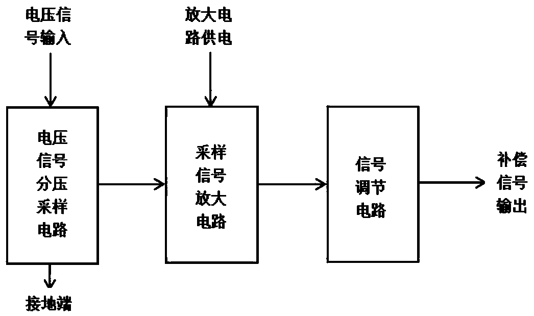
[0047] Figure 4 The overcurrent protection compensation circuit of the first implementation example of the present invention includes a voltage signal sampling voltage divider circuit, a sampling signal amplification circuit and a signal adjustment circuit.
[0048] The voltage signal sampling voltage dividing circuit is composed of four components including a resistor R1, a resistor R2, a resistor R3 and a capacitor C1. The three devices of resistor R1, resistor R2 and resistor R3 are connected in series, and one port of resistor R1 is connected to the sampling input terminal of the input voltage signal. The other end is connected to resistor R2; one end of resistor R2 is connected to resistor R1, the other end is connected to resistor R3 and capacitor C1; one end of resistor R3 is connected to resistor R2 and capacitor C1, and the other end is connected to circuit ground; one end of capacitor C1 is connected to To the ground wire of the circuit, while the other end is conn...
no. 2 example
[0058] Figure 5 It is the compensation circuit for overcurrent protection in the second embodiment of the present invention. The main circuit is the same as the first embodiment. The difference from the first embodiment is that the input voltage signal is sampled from the low-voltage signal output from the auxiliary winding of the power supply after rectification. DC VCC. A compensating circuit for overcurrent protection includes a voltage signal sampling and dividing circuit, a sampling signal amplifying circuit and a signal adjusting circuit.
[0059] The voltage signal sampling voltage dividing circuit is composed of four components including a resistor R1, a resistor R2, a resistor R3 and a capacitor C1. Resistor R1, resistor R2, and resistor R3 are connected in series. One port of resistor R1 is connected to the sampling input terminal of the input voltage signal. The voltage signal sampled by the input voltage signal comes from the voltage signal VCC rectified by the a...
no. 3 example
[0064] Figure 6 It is the compensation circuit for overcurrent protection of the third embodiment of the present invention, the main circuit is the same as the first embodiment, and the difference from the first embodiment is that the power supply of the sampling signal amplification circuit of the third embodiment comes from the power control chip The reference voltage output port Vref. The advantage of this embodiment compared with the first embodiment is that the power supply of the sampling signal amplification circuit comes from the reference voltage output port Vref of the power control chip. The voltage of this port is relatively more stable than VCC, and the operation of the amplification circuit is not affected by the fluctuation of VCC caused by the outside world. Influence, so the work of the amplifier circuit is more stable.
PUM
 Abstract
Description
Claims
Application Information
 - R&D
- Intellectual Property
- Life Sciences
- Materials
- Tech Scout
- Unparalleled Data Quality
- Higher Quality Content
- 60% Fewer Hallucinations
Browse by: Latest US Patents, China's latest patents, Technical Efficacy Thesaurus, Application Domain, Technology Topic, Popular Technical Reports.
© 2025 PatSnap. All rights reserved.Legal|Privacy policy|Modern Slavery Act Transparency Statement|Sitemap|About US| Contact US: help@patsnap.com


