Tourniquet mechanism and tourniquet

A tourniquet and pulse pressing technology, applied in the field of medical equipment, can solve the problems of high labor intensity, inconvenience, and high cost

Pending Publication Date: 2018-12-21
磅客策(上海)智能医疗科技有限公司
View PDF0 Cites 6 Cited by
  • Summary
  • Abstract
  • Description
  • Claims
  • Application Information

AI Technical Summary

Problems solved by technology

[0008] The first purpose of the present invention is to provide a pressure cuff mechanism to alleviate the technical problems of inconvenience, labor intensity and high cost caused by manual tightening of the cuff in the prior art

Method used


Image

  • Tourniquet mechanism and tourniquet
  • Tourniquet mechanism and tourniquet
  • Tourniquet mechanism and tourniquet

Examples


Embodiment 1

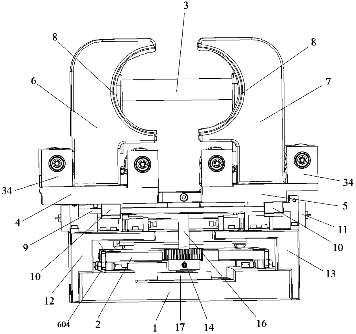
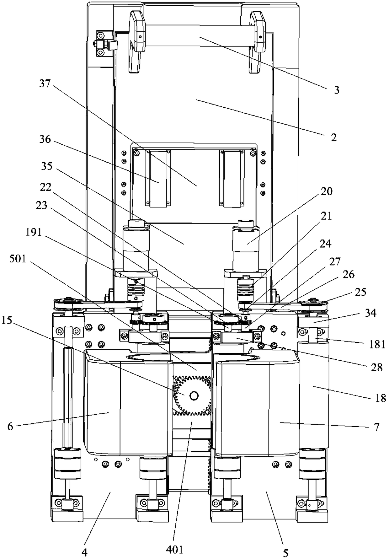
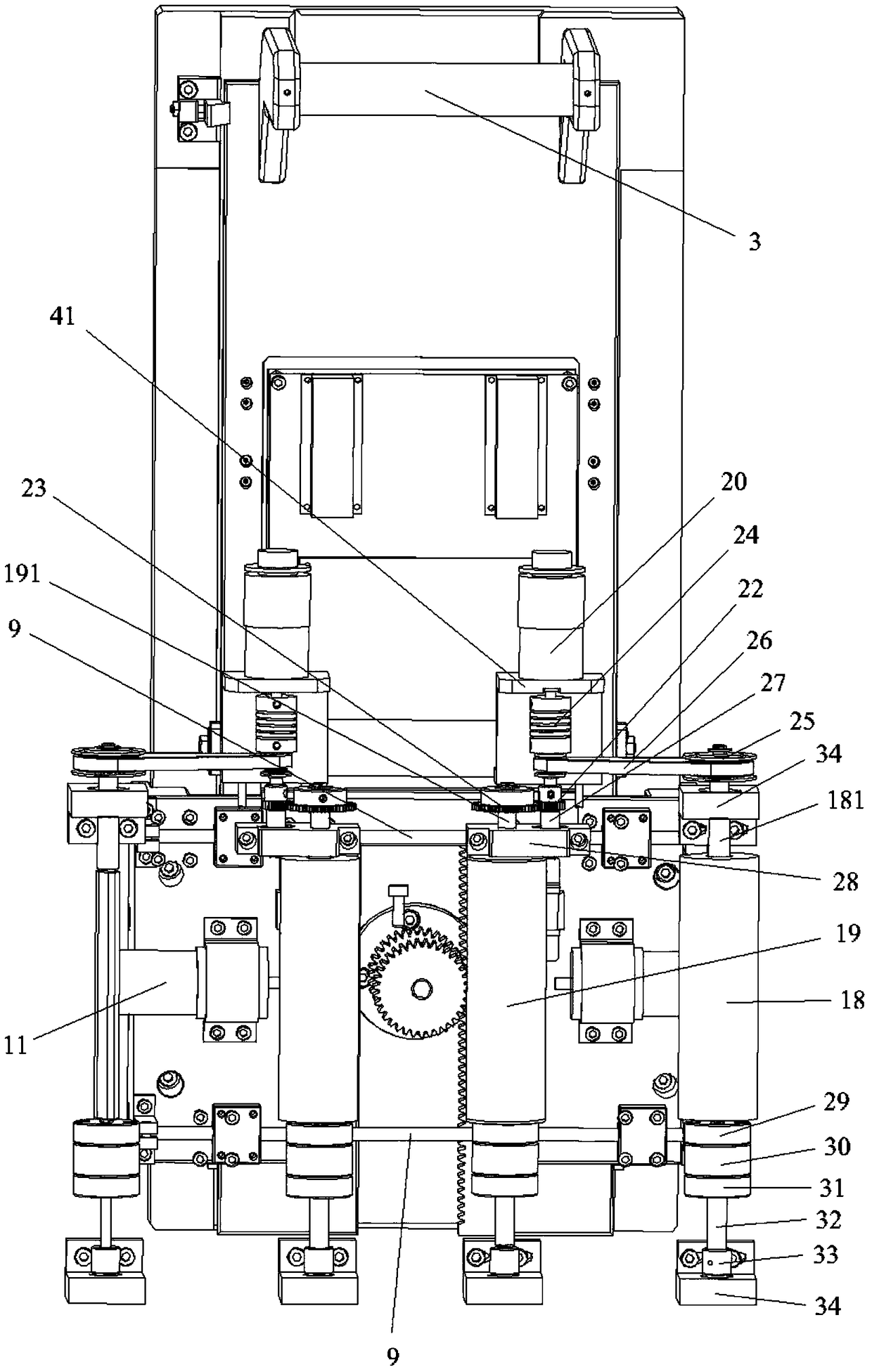
[0040] Such as figure 1 As shown in -6, the cuff mechanism provided by Embodiment 1 of the present invention includes: a left cuff mechanism and a right cuff mechanism arranged symmetrically; the left cuff structure includes a cuff left bottom plate 4 and a cuff left plate 6. The left base plate 4 of the tourniquet can be slidably arranged on the base 1 of the tourniquet, the left side plate 6 of the tourniquet is arranged on the left base plate 4 of the tourniquet, and a C-shaped groove 8 is opened on the left side plate 6 of the tourniquet; the right tourniquet structure includes a tourniquet The right bottom plate 5 for the pulse control and the right side plate 7 for the cuff, the right bottom plate for the cuff 5 is arranged on the base 1 of the tourniquet, the right side plate 7 for the cuff can be slidably arranged on the right bottom plate 5 for the cuff, and the right side plate 7 for the cuff A C-shaped groove 8 is provided. Wherein, the cuff left base plate 4 is sl...

Embodiment 2

[0052] This embodiment provides a membrane-changing tourniquet, which is used in medical measures such as blood collection and infusion from human veins in hospitals, which can realize the optimization of pulse pressing and the replacement of the hygienic membrane on the tourniquet, and effectively avoid the problem of cross-infection in blood collection. Such as figure 1 - image 3 As shown, the tourniquet replacement device includes a tourniquet base 1, a left tourniquet structure, a right tourniquet structure and a membrane replacement structure, wherein both the left tourniquet structure and the right tourniquet structure are arranged on the tourniquet base 1 , the left cuff structure and the right cuff structure are respectively provided with a C-shaped groove 8, the left cuff structure and the right cuff structure can slide relative to each other so that the two C-shaped grooves 8 can wrap the arms, and the two C-shaped grooves 8 are close to each other After sliding, t...

Embodiment 3

[0064] Embodiment 3 of the present invention also provides a tourniquet, including the supporting structure provided in Embodiment 1.

[0065] Specifically, the tourniquet base 1, one end of the tourniquet base 1 is fixed with a tourniquet support by screws;

[0066] The tourniquet support, the tourniquet support is two right-angled plates with the same structure: the tourniquet left support 12, the tourniquet right support 13, the left and right support 13 of the tourniquet are respectively connected with an arch by screws shaped mounting frame, an air pump 11 is fixed in the arched mounting frame; one end of the tourniquet support is fixed with a circuit support plate by screws, and a brush motor drive plate is fixed on the circuit support plate, and a brush motor drive plate is fixed on the circuit support plate. A circuit board partition 37 is installed and fixed by studs, and the circuit board partition 37 includes STM32 and relay module 36;

[0067] A transmission base ...


PUM


Abstract

The invention provides a tourniquet mechanism and a tourniquet, and relates to the technical field of medical instruments. The tourniquet mechanism comprises a left tourniquet mechanism body and a right tourniquet mechanism body; the left tourniquet mechanism body comprises a left tourniquet bottom plate and a left tourniquet side plate, the left tourniquet bottom plate is slidingly arranged on atourniquet base, the left tourniquet side plate is arranged on the left tourniquet bottom plate, and a C-type groove is formed in the left tourniquet side plate; the right tourniquet mechanism body comprises a right tourniquet mechanism body and a right tourniquet side plate, the right tourniquet mechanism body is arranged on the tourniquet base, the right tourniquet side plate is arranged on theright tourniquet bottom plate, and a C-type groove is formed in the right tourniquet side plate. The aim is to solve the technical problems that in the prior art, when tourniquet cuff is fastened manually, inconvenience is generated, labor intensity is high, and costs are high.

Description

technical field [0001] The invention relates to the technical field of medical devices, in particular to a tourniquet mechanism and a tourniquet. Background technique [0002] At present, the commonly used compression hemostasis for internal fistula mainly uses gauze blocks, buttons, gauze rolls covered with finger cots, toilet paper pads, cuffs with self-contained cuffs and other devices for compression hemostasis, or medical staff directly use fingers Apply pressure to stop bleeding. The deficiencies of current hemostatic devices mainly include: [0003] The gauze piece is a rectangular cloth pad, and the contact with the compression point is flat, the compression force is poor, the filling of the depression is insufficient, and it is easy to ooze blood or subcutaneous hematoma, and once the gauze piece is contaminated by blood, it will become soft immediately, and the effect of compression and hemostasis will be directly affected. influences. [0004] Because the butto...

Claims


Application Information

Patent Timeline
Patent Type & Authority Applications(China)
IPC IPC(8): A61B17/12
CPCA61B17/12A61B2017/12004
Inventor 乔徽高强张兆东马兆彬吕银庄王博朱曦颛孙伟
Owner 磅客策(上海)智能医疗科技有限公司
Why Eureka
Try Eureka