Overturning method for mechanically clamping long steel structural parts

A technology for structural parts and long steel, which is applied in the field of turning over mechanically clamped long steel structural parts, can solve problems such as production difficulties, oil leakage, oil leakage, etc. Effect

Inactive Publication Date: 2018-12-21
陈海锋
View PDF1 Cites 5 Cited by
  • Summary
  • Abstract
  • Description
  • Claims
  • Application Information

AI Technical Summary

Problems solved by technology

[0002] With China's continuous exploration of the ocean and the continuous upgrading of ships and marine engineering products, the application of large I-beams, box girders, and racks continues to increase, the weight of workpieces increases, the requirements for size increase, and the requirements for welding processes are more stringent. Strictly, these racks, I-beams, box beams and other steel structures with small cross-sectional areas and long longitudinal lengths often need to be carried out in a specific order or symmetrical direction during the production process of welding, riveting, etc., especially In the field of marine engineering, the welding of large racks has higher requirements for overturning. The traditional method uses floor-mounted or integrated hydraulic clamping and overturning mechanisms, which is inefficient, and the hydraulic cylinder will inevitably leak after long-term use. Oil or oil leakage brings unnecessary difficulties to production. In the prior art, for example, the invention patent with application number 201220514663.1 includes a base and two supporting frames, which are installed on the base to support the long steel structure respectively. The end of the long steel structure is suspended, the rotating device is symmetrically arranged on the two support frames, the locking device is fixed on the rotating device, and the axial and radial direction is fixed. The steel structure, the electric drive control device, is installed on one of the two supporting frames and is electrically connected to the rotating device on the supporting frame. Although the structure of this invention is simple, there are many deficiencies and defects. In some equipment, there are defects in the design of the locking device, the connection between the clamping body and the steel structure is unstable, and the steel structure itself will sink due to its own gravity, causing the clamping body to be subjected to the downward bearing force and cause the clamping body to break down. The deformation cannot be turned over normally, which will easily cause damage to the turning device, and the clamping body can only be fixed and drive a steel structural member to turn over. The use function is single, which reduces the processing efficiency and increases the processing cost. When using it, it is easy for the operator to have Work fatigue, reduce work efficiency, in view of these situations, in order to avoid the above-mentioned technical problems, it is necessary to provide a kind of flipping method for mechanically clamping long steel structures to overcome the defects in the prior art

Method used


Image

  • Overturning method for mechanically clamping long steel structural parts
  • Overturning method for mechanically clamping long steel structural parts
  • Overturning method for mechanically clamping long steel structural parts

Examples


Embodiment Construction

[0019] The following will clearly and completely describe the technical solutions in the embodiments of the present invention with reference to the accompanying drawings in the embodiments of the present invention. Obviously, the described embodiments are only some, not all, embodiments of the present invention. Based on the embodiments of the present invention, all other embodiments obtained by persons of ordinary skill in the art without making creative efforts belong to the protection scope of the present invention.

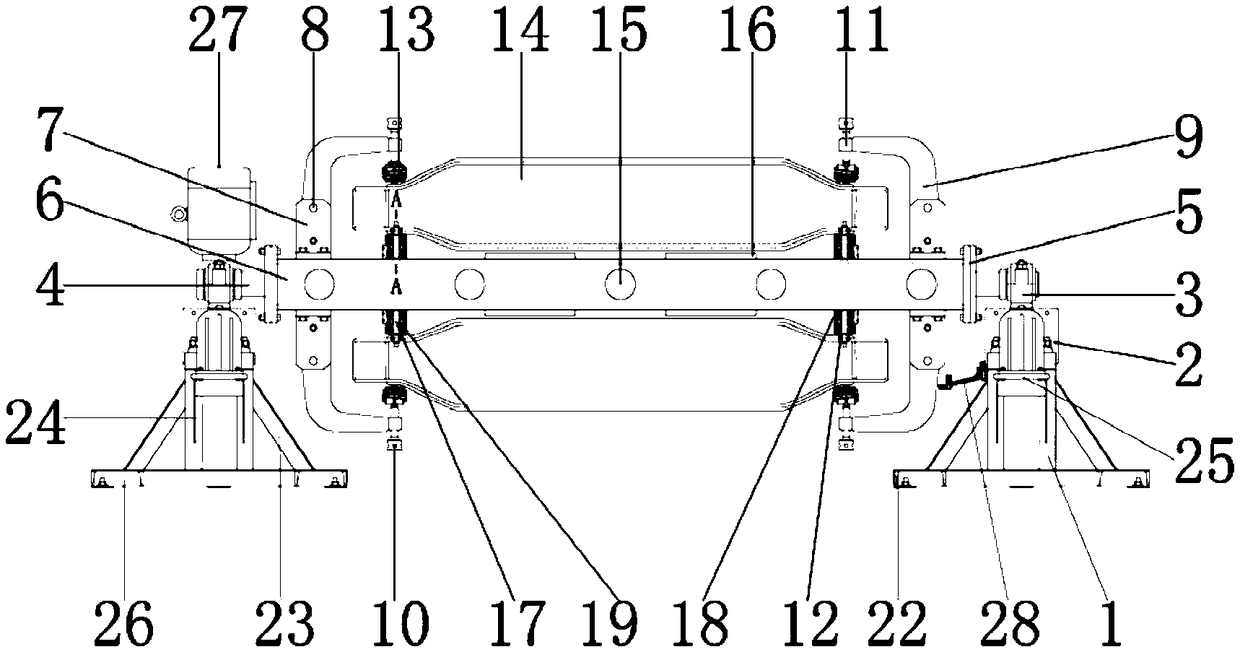
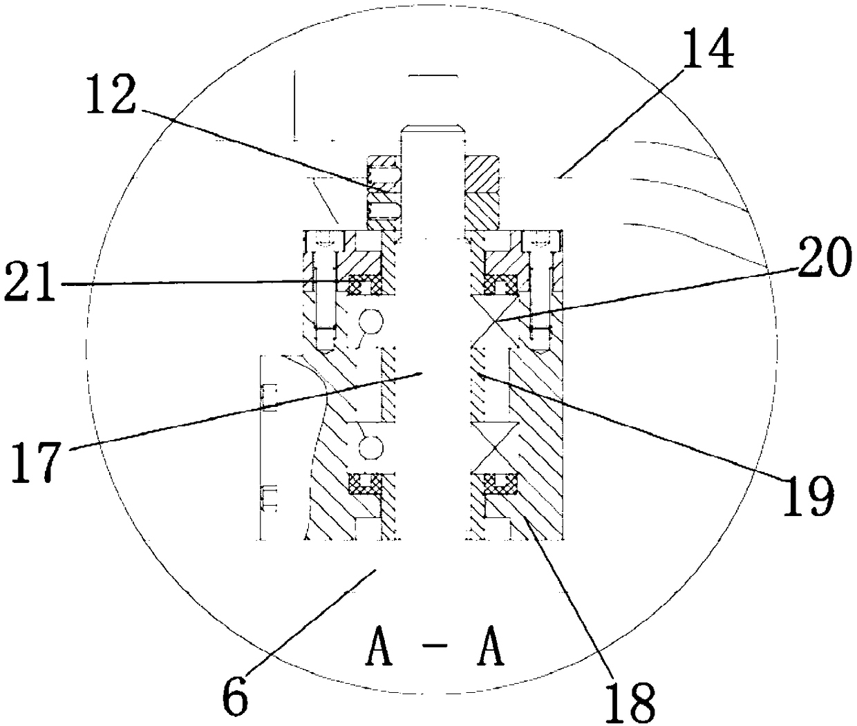
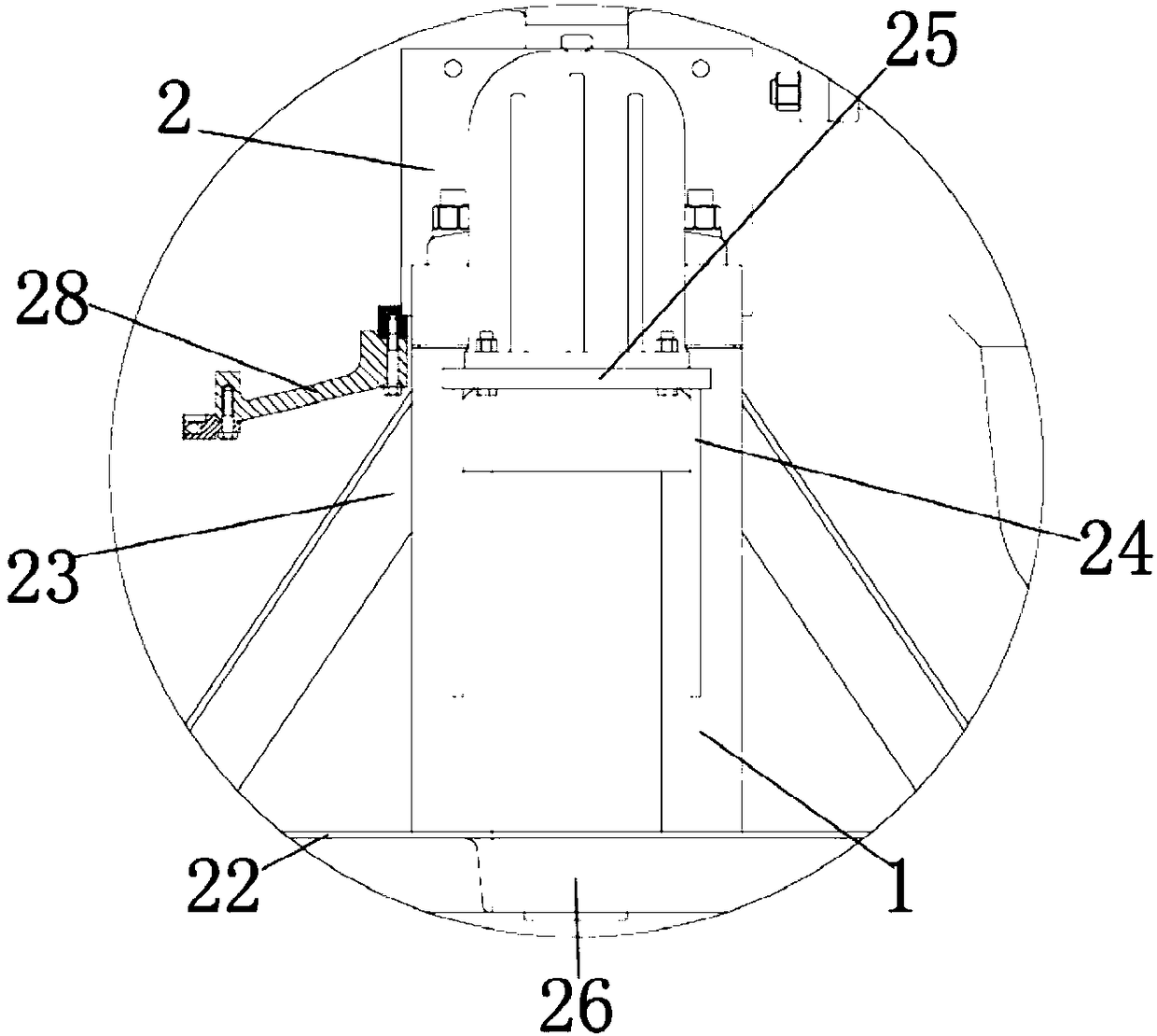
[0020] see Figure 1-3, the present invention provides a technical solution: a flipping method for mechanically clamping a long steel structure, including a leg 1, the leg 1 is used to install and fix the bracket 2, and the left and right sides of the outer wall of the leg 1 are installed There are inclined steel bars 23 for strengthening the connection between the support leg 1 and the bracket 2, the inner wall of the inclined steel bar 23 is connected with t...


PUM


Abstract

The invention discloses an overturning method for mechanically clamping long steel structural parts. A motor 27 is connected with a rotating wheel 3; a rotating shaft 4 is connected with the rotatingwheel 3; a rotating rod 6 is connected with the rotating shaft 4 by using a connecting flange 5, so that an external power supply of a motor 27 is electrified; the motor 27 is started to work; the motor 27 drives the rotating wheel 3 to rotate; the rotating wheel 3 drives the rotating shaft 4 to rotate during rotating; the rotating shaft 4 drives the connecting flange 5 to rotate during rotating;the connecting flange 5 is connected with the rotating rod 6; the connecting flange 5 drives the rotating rod 6 to rotate during rotating; the rotating wheel 3 is fixed on a bracket 2; the bracket 2 is supported by using support legs 1 to reach a certain height from the ground, so that machined parts 14 are conveniently driven to overturn by the motor 27; ejector bases 7 are mounted on two sides of the outer wall of the rotating rod 6; pin shafts 8 are mounted in the ejector bases 7; crankshafts 9 are mounted in the ejector bases 7; the crankshafts 9 can be driven by the pin shafts 8 to incline; the machined parts 14 are fixed; and stoppers 13 are mounted on the crankshafts 9. Therefore, the assembly work of an overturning device for mechanically clamping the long steel structural parts.

Description

technical field [0001] The invention relates to the technical field of steel structures, in particular to a flipping method for mechanically clamping long steel structures. Background technique [0002] With China's continuous exploration of the ocean and the continuous upgrading of ships and marine engineering products, the application of large I-beams, box girders, and racks continues to increase, the weight of workpieces increases, the requirements for size increase, and the requirements for welding processes are more stringent. Strictly, these racks, I-beams, box beams and other steel structures with small cross-sectional areas and long longitudinal lengths often need to be carried out in a specific order or symmetrical direction during the production process of welding, riveting, etc., especially In the field of marine engineering, the welding of large racks has higher requirements for overturning. The traditional method uses floor-mounted or integrated hydraulic clampi...

Claims


Application Information

Patent Timeline
Patent Type & Authority Applications(China)
IPC IPC(8): B23K37/047
CPCB23K37/047
Inventor 陈海锋
Owner 陈海锋
Why Eureka
Try Eureka