Mechanical arm system and control method of mechanical arm system

A manipulator and square column technology, applied in the field of manipulators, can solve the problems of low production capacity, low degree of automation, and inability to achieve high-precision transfer of processed workpieces.

Inactive Publication Date: 2018-12-21
东莞仕达通自动化有限公司
View PDF7 Cites 3 Cited by
  • Summary
  • Abstract
  • Description
  • Claims
  • Application Information

AI Technical Summary

Problems solved by technology

The above-mentioned scheme realizes diverting transportation to a certain extent, but this scheme still has the following defects at least: first, it cannot realize the high-precision transfer of the processed workpiece; second, there are problems of low degree of automation and low production capacity; third, The manipulator has the disadvantages of simple structure and imperfect function

Method used


Image

  • Mechanical arm system and control method of mechanical arm system
  • Mechanical arm system and control method of mechanical arm system

Examples


Embodiment 1

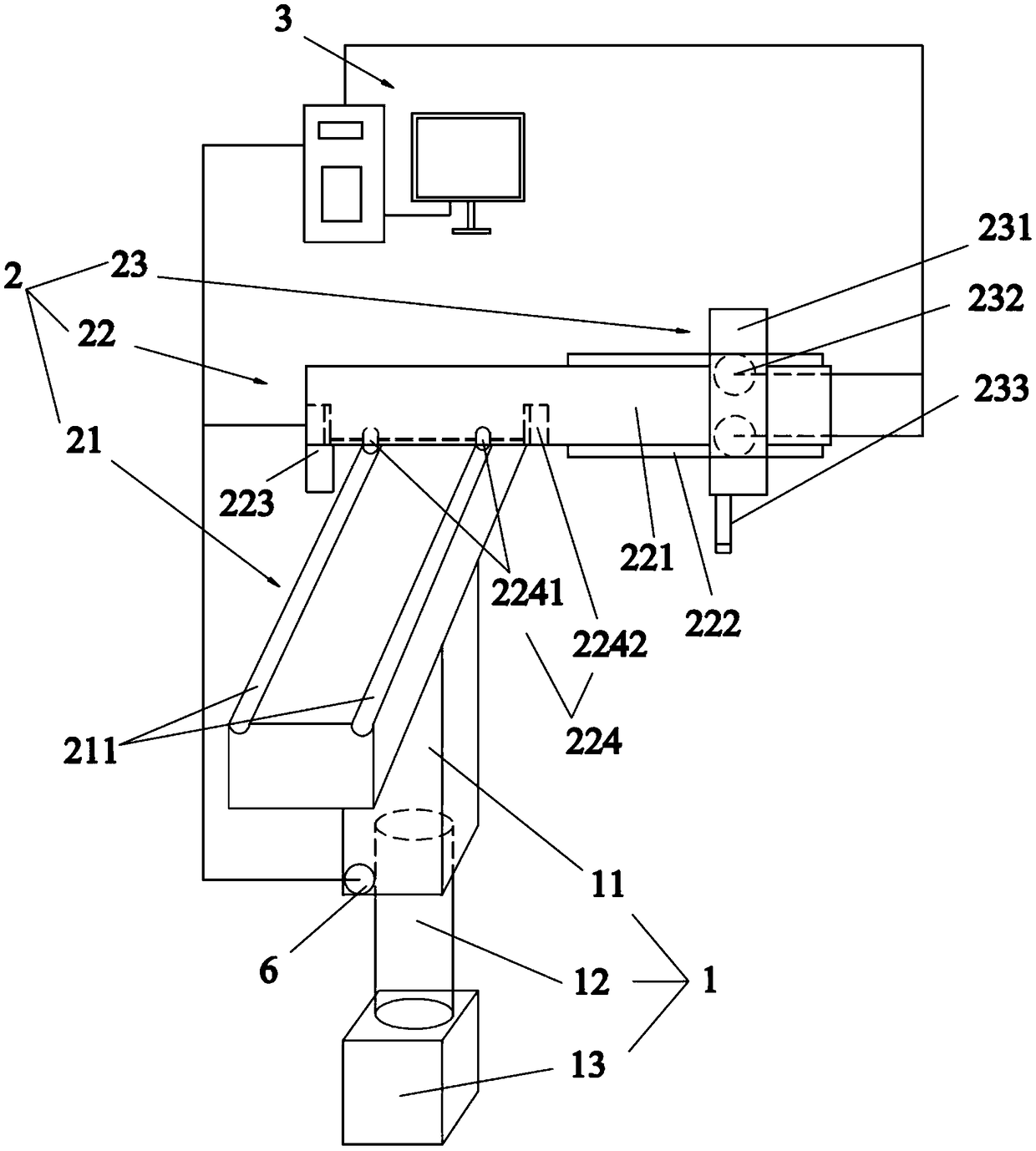
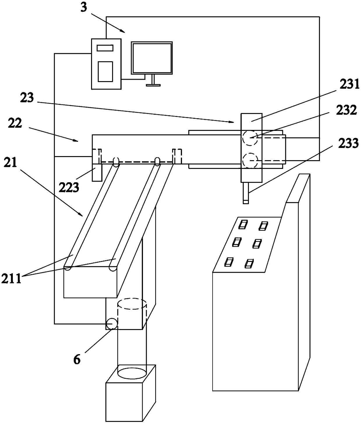
[0028] Such as Figure 1~2 As shown, the manipulator system includes a lifting device 1, a plane kinematic mechanism 2 and a computer 3, and the lifting device 1 and the plane kinematic mechanism 2 are electrically connected to the computer 3, and the plane kinematic mechanism 2 includes a load longitudinal beam 21, a movable beam 22 and Replaceable operating part 23, the beam 22 is slidingly connected to the load longitudinal beam 21, and the operating part 23 is slidingly connected to the beam 22. The operating part 23 includes a main body 231, an electric wheel 232 arranged in the main body 231 and a manipulator 233 fixed to the main body 231 . The crossbeam 22 is slidably connected with the load longitudinal beam 21, which helps to realize the forward and backward movement of the crossbeam 22, and the sliding connection between the operation part 23 and the crossbeam 22, which helps to realize the left and right movement of the operation part 23, and the movable crossbeam ...

Embodiment 2

[0033] The difference from Embodiment 1 is that the manipulator 233 in this embodiment is a mechanical claw for grabbing heavy objects. In the logistics industry, the height of the shelf limits the storage capacity of the warehouse. Using a manipulator system with mechanical claws can put heavier goods on higher shelves and increase the storage capacity of the warehouse.

[0034] Other structures are the same as those in Embodiment 1, and will not be repeated here.

Embodiment 3

[0036] The difference from Embodiment 1 is that the manipulator 233 in this embodiment is an electric drill used for drilling. In the circuit board drilling industry, the efficiency of manual drilling is low and the accuracy is relatively low. Using a manipulator system with an electric drill can improve the accuracy of drilling and the efficiency of drilling.

[0037] Other structures are the same as those in Embodiment 1, and will not be repeated here.


PUM


Abstract

The invention belongs to the technical field of mechanical arms, and particularly relates to a mechanical arm system. The mechanical arm system comprises a lifting device (1), a plane motion mechanism(2) and a computer (3); the lifting device (1) and the plane motion mechanism (2) are electrically connected with the computer (3), the plane motion mechanism (2) comprises a bearing longitudinal beam (21), a movable cross beam (22) and a replaceable operation part (23), the movable cross beam (22) and the bearing longitudinal beam (21) are in sliding connection, and the operation part (23) is insliding connection with the movable cross beam (22). The mechanical arm system has the expanding and practicability, the mechanical arm can be flexibly controlled to finish corresponding actions, high-precision moving can be achieved, the automatic mechanical operation can be achieved, work efficiency is improved, manual cost is reduced, and in addition, the invention discloses a control method of the mechanical arm system.

Description

technical field [0001] The invention belongs to the technical field of manipulators, and in particular relates to a manipulator system and a control method for the manipulator system. Background technique [0002] A manipulator is an automatic operating device that can imitate certain movement functions of the human hand and arm, and can grasp, carry objects or operate tools according to a fixed program. It can replace human heavy labor to realize the mechanization and automation of production, and can operate in harmful environments to protect personal safety, so it is widely used in machinery manufacturing, metallurgy, electronics, light industry and atomic energy and other departments. At present, in the manufacturing industry, most of the manual production is based on a single process, resulting in low production capacity, unstable quality, high scrap rate, and insufficient industrial efficiency. It is also dangerous and far from meeting the production requirements. nee...

Claims


Application Information

Patent Timeline
Patent Type & Authority Applications(China)
IPC IPC(8): B25J9/16B25J9/02B25J15/04
CPCB25J9/02B25J9/1664B25J15/0475
Inventor 萧进展余尚武凃英杰
Owner 东莞仕达通自动化有限公司
Why Eureka
Try Eureka