Manipulator mechanism and robot

A technology of manipulators and reducers, applied in manipulators, chucks, manufacturing tools, etc., can solve the problems that the side walls cannot be too soft, too slippery, inapplicable, and poor in adaptability, so as to improve the scope of use, applicability, and scope of application. The effect of increasing and decreasing the occupied space

Inactive Publication Date: 2018-12-21
GUANGDONG MIDEA INTELLIGENT ROBOTICS CO LTD
View PDF6 Cites 0 Cited by
  • Summary
  • Abstract
  • Description
  • Claims
  • Application Information

AI Technical Summary

Problems solved by technology

[0002] In related technologies, there are two types of manipulator mechanisms: the first type is to grab materials by means of top suction, and its mechanical structure part is above the material, but the mechanical structure part of this type of manipulator mechanism is above the material. The space is huge, and at the same time, placing the material also requires a huge space above the target position, which makes it unsuitable for limited space on the top of the material, and this type of manipulator mechanism also requires the top of the material to have a good shape and flatness , not applicable when the top of the material is messy or loose
The second type is to grab the material by squeezing the side wall of the material and holding the material tightly. The mechanical structure of this type of manipulator mechanism is also above the material, which also requires a large space on the top of the material and has a certain impact on the rigidity of the material side wall. Certain requirements, at least one pair of side walls should not be too soft and slippery, and the symmetrical clamping method requires sufficient space on both sides of the material, which has poor adaptability

Method used


Image

  • Manipulator mechanism and robot
  • Manipulator mechanism and robot
  • Manipulator mechanism and robot

Examples


Embodiment Construction

[0039] In order to understand the above-mentioned purpose, features and advantages of the present invention more clearly, the present invention will be further described in detail below in conjunction with the accompanying drawings and specific embodiments. It should be noted that, in the case of no conflict, the embodiments of the present application and the features in the embodiments can be combined with each other.

[0040] In the following description, many specific details are set forth in order to fully understand the present invention. However, the present invention can also be implemented in other ways than described here. Therefore, the protection scope of the present invention is not limited by the specific implementation disclosed below. Example limitations.

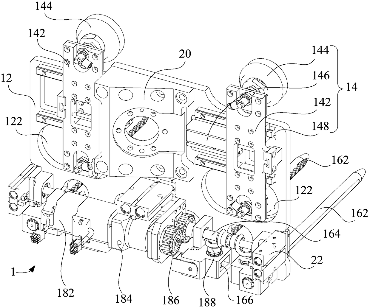
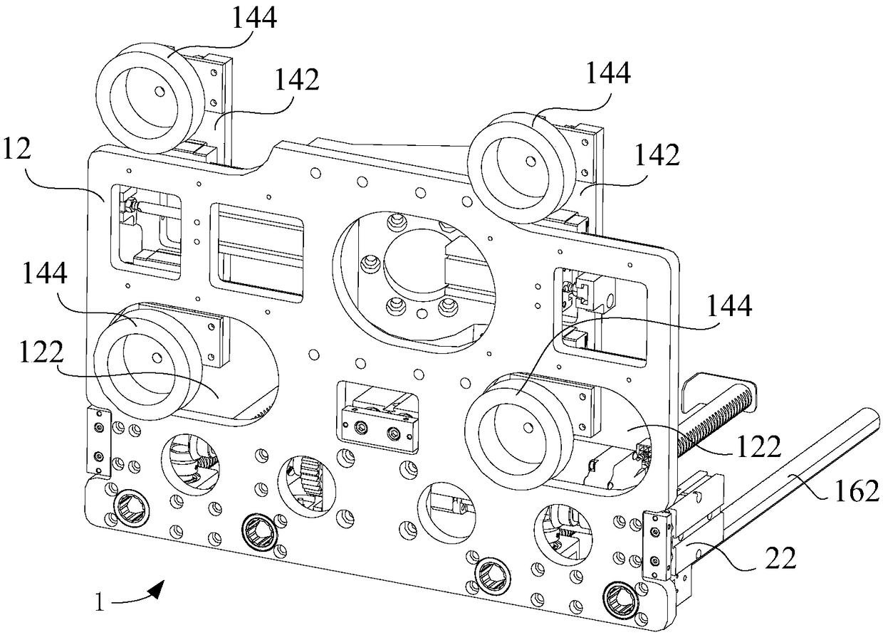
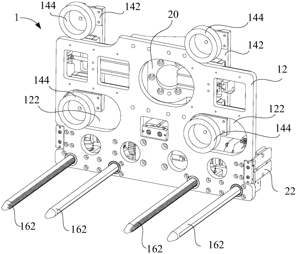
[0041] Refer below Figure 1 to Figure 3 The manipulator mechanism 1 and the robot provided according to some embodiments of the present invention will be described.

[0042] The first aspect of the present...


PUM


Abstract

The invention provides a manipulator mechanism and a robot. The manipulator mechanism comprises a mounting plate; a suction cup assembly, a driving system and a guiding shaft assembly. The suction cupassembly is movably arranged on the mounting plate. The driving system is arranged on the mounting plate. The guiding shaft assembly is connected with the driving system. A guiding shaft in the guiding shaft assembly extends to the work position or retracts to the original position under driving of the driving system, wherein the original position and the work position are located on the two opposite sides of the mounting plate. The guiding shaft located at the work position and a suction cup in the suction cup assembly are located on the same side. The manipulator mechanism provided by the invention does not occupy the top space of materials, has low requirements for a working place, can achieve material arrangement in a limited space, has low requirements for material properties and thespace environment where the materials are located, and has high adaptability.

Description

technical field [0001] The invention relates to the technical field of logistics equipment, in particular to a manipulator mechanism and a robot. Background technique [0002] In the related technology, there are two types of manipulator mechanisms: the first type is to grab materials by top suction, and its mechanical structure part is above the material, but the mechanical structure part of this type of manipulator mechanism is above the material. The space is huge, and at the same time, placing the material also requires a huge space above the target position, which makes it impossible to apply when the space on the top of the material is limited, and this type of manipulator mechanism also requires the top of the material to have a good shape and flatness , not applicable when the top of the material is messy or loose. The second type is to grab the material by squeezing the side wall of the material and holding the material tightly. The mechanical structure of this typ...

Claims


Application Information

Patent Timeline
Patent Type & Authority Applications(China)
IPC IPC(8): B25J15/00B25J15/06
CPCB25J15/00B25J15/0683
Inventor 梁耀棠李建韬莫永志黄善胜
Owner GUANGDONG MIDEA INTELLIGENT ROBOTICS CO LTD
Why Eureka
Try Eureka