
Lead screw lifting high-speed roller bed for conveying

A technology of screw lifting and conveying rollers, applied to conveyor objects, conveyor control devices, roller tables, etc., can solve problems such as difficulty in realizing multi-model co-line production, inappropriate coordination with various peripheral equipment, and large footprint. , to increase multi-model mixed production, reduce takt time loss, and achieve the effect of small footprint

Inactive Publication Date: 2018-12-21
广州德恒汽车装备科技有限公司
View PDF7 Cites 7 Cited by
  • Summary
  • Abstract
  • Description
  • Claims
  • Application Information

AI Technical Summary

Problems solved by technology

[0002] With the continuous improvement of the scientific level and the continuous growth of people's needs, the rapid development of the automobile industry and the rapid expansion of automobile production scale have led to higher requirements for production equipment, but are currently serving the production systems of major automobile manufacturers. The high-speed roller bed conveying equipment has the following disadvantages: 1. It occupies a large area and is not suitable for a variety of peripheral equipment, such as multi-axis positioning devices and windmill positioning devices; 2. Poor flexibility, the welding line in the welding workshop is subject to Due to the limitation of special fixtures for each model, it is difficult to achieve multi-model collinear production while ensuring the production cycle

Method used


Image

  • Lead screw lifting high-speed roller bed for conveying
  • Lead screw lifting high-speed roller bed for conveying
  • Lead screw lifting high-speed roller bed for conveying

Examples


Embodiment Construction

[0027] The specific embodiments of the present invention will be described in detail below in conjunction with the accompanying drawings, but it should be understood that the protection scope of the present invention is not limited by the specific embodiments.

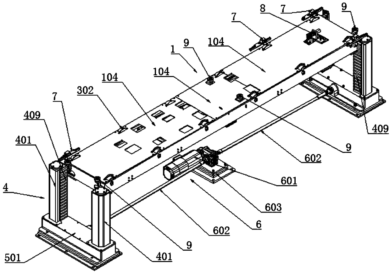
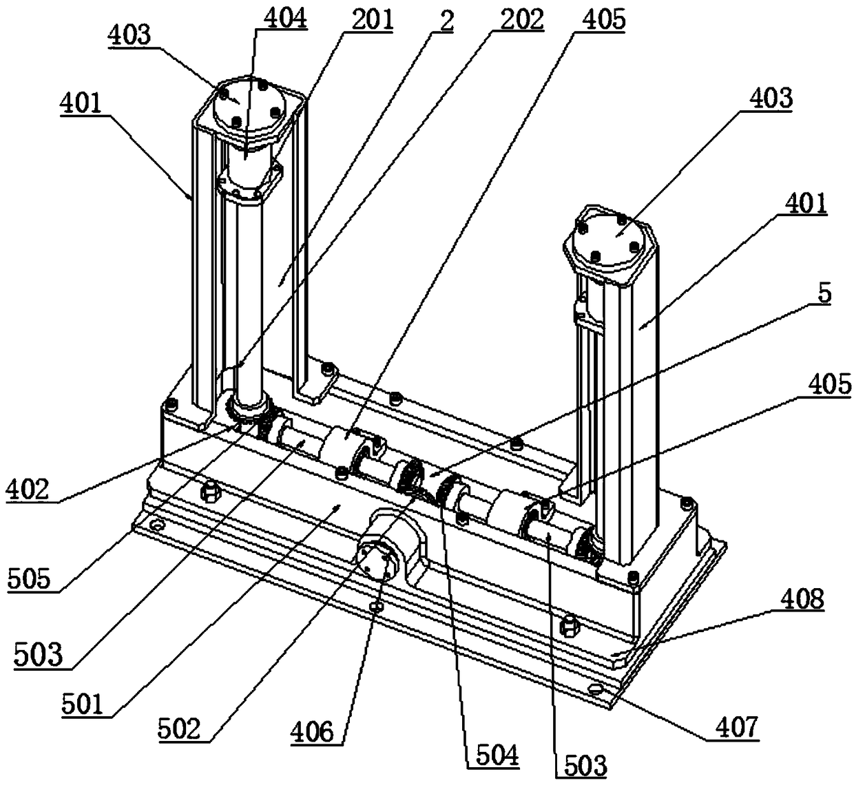
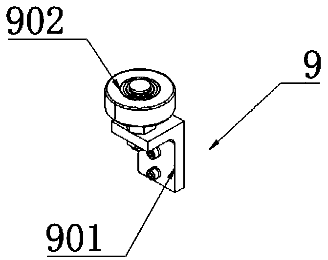
[0028] The specific embodiment of the present invention is like this: as Figure 1-5 As shown, a screw mandrel lifting high-speed roller bed for conveying comprises a conveying roller bed 1 and two supporting frames 4 arranged at both ends of the conveying roller bed 1, and each supporting frame 4 is provided with a support frame for supporting the conveying roller bed 1. Lead screw lifting mechanism 2, a lifting drive device 6 capable of driving two lead screw lifting mechanisms 2 is provided under the conveying roller bed 1, and a steering conversion mechanism connecting the lead screw lifting mechanism 2 with the lifting drive device 6 is provided on the support frame 4 5. The steering conversion mechanism 5 is inte...


PUM


Abstract

The invention discloses a lead screw lifting high-speed roller bed for conveying. The lead screw lifting high-speed roller bed comprises a conveying roller bed and two supporting frames arranged at the two ends of the conveying roller bed, each of the supporting frames is provided with a lead screw lifting mechanism for supporting the conveying roller bed, a lifting drive device capable of drivingthe two lead screw lifting mechanisms is arranged below the conveying roller bed, steering conversion mechanisms for connecting the lead screw lifting mechanisms with the lifting drive device are arranged on the supporting frames, a horizontal conveying mechanism is arranged on the conveying roller bed, a plurality of sensing devices for sensing the positions of workpieces are arranged on the side of the conveying roller bed, and the conveying roller bed is provided with a safety stopping device capable of ascending and descending. The lead screw lifting high-speed roller bed for conveying issmall in floor space and is suitable for cooperating with various peripheral devices such as a multi-axis positioning device and a windmill positioning device.

Description

technical field [0001] The invention relates to the technical field of automobile production and transportation, more specifically, it relates to a high-speed roller bed for lifting and lowering by a screw rod for transportation. Background technique [0002] With the continuous improvement of the scientific level and the continuous growth of people's needs, the rapid development of the automobile industry and the rapid expansion of automobile production scale have led to higher requirements for production equipment, but are currently serving the production systems of major automobile manufacturers. The high-speed roller bed conveying equipment has the following disadvantages: 1. It occupies a large area and is not suitable for a variety of peripheral equipment, such as multi-axis positioning devices and windmill positioning devices; 2. Poor flexibility, the welding line in the welding workshop is subject to Due to the limitation of special fixtures for each model, it is dif...

Claims


Application Information

Patent Timeline
Patent Type & Authority Applications(China)
IPC IPC(8): B65G13/07B65G13/12B65G43/08
CPCB65G13/07B65G13/12B65G43/08
Inventor 王磊惠智刚黎庆灵黄海周逸群邓伟东
Owner 广州德恒汽车装备科技有限公司
Learn More