
A multi-model welding fixture frame connection mechanism

A connection mechanism and welding fixture technology, which is applied in the field of welding fixture frame connection and welding fixture frame connection mechanism, can solve the problems that the fixture frame is in the cantilever beam state and the spot welding is inaccurate, and solves the problem of multi-vehicle collinear Production difficulties, improved welding accuracy, and improved rigidity

Active Publication Date: 2015-12-16
GUANGZHOU MINO AUTOMOTIVE EQUIP CO LTD +1
View PDF7 Cites 0 Cited by
  • Summary
  • Abstract
  • Description
  • Claims
  • Application Information

AI Technical Summary

Problems solved by technology

The fixture frame in the existing welding fixture frame connection mechanism generally adopts one-sided installation of the fixture, causing the fixture frame to be in a cantilever beam state
During the body welding process, due to the force of the welding torch, the fixture frame moves with the body, which makes the spot welding inaccurate

Method used


Image

  • A multi-model welding fixture frame connection mechanism
  • A multi-model welding fixture frame connection mechanism
  • A multi-model welding fixture frame connection mechanism

Examples


Embodiment Construction

[0023] The idea, specific structure and technical effects of the present invention will be clearly and completely described below in conjunction with the embodiments and accompanying drawings, so as to fully understand the purpose, features and effects of the present invention. Apparently, the described embodiments are only some of the embodiments of the present invention, rather than all of them. Based on the embodiments of the present invention, other embodiments obtained by those skilled in the art without creative efforts belong to The protection scope of the present invention. In addition, all the connection / connection relationships mentioned in this article do not refer to the direct connection of components, but mean that a better connection structure can be formed by adding or reducing connection accessories according to specific implementation conditions.

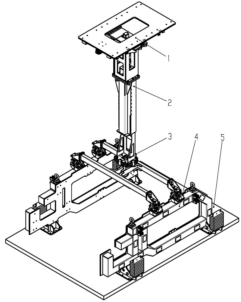
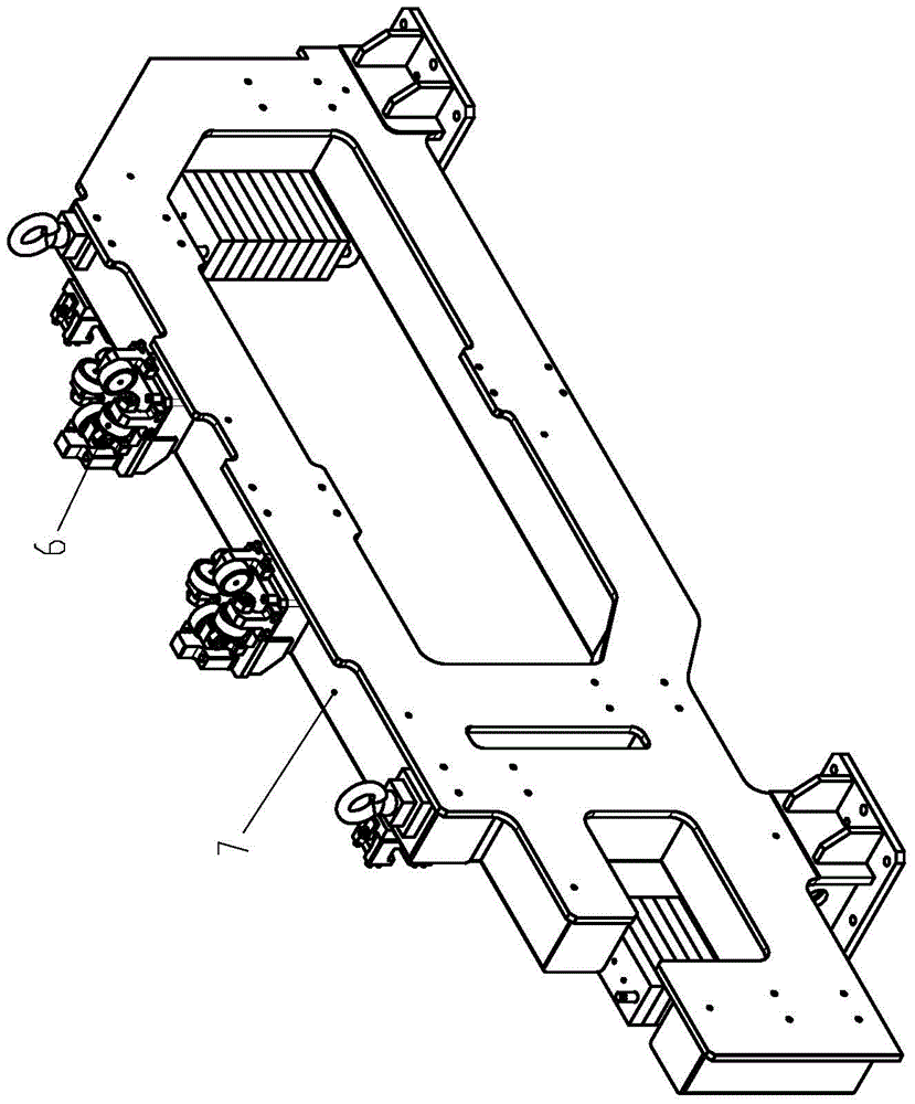
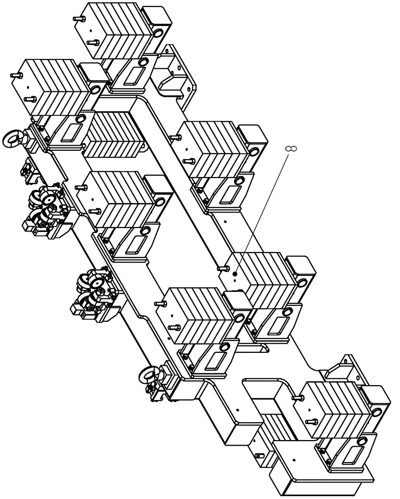
[0024] refer to Figure 1 to Figure 8 , a multi-vehicle welding fixture frame connection mechanism, which inclu...


PUM


Abstract

The invention discloses a multi-vehicle-type welding fixture frame connecting mechanism which comprises a system mounting plate, two fixture frame units arranged on the system mounting plate in parallel and a connecting mechanism positioning unit erected on the fixture frame units in a crossing mode. The upper end face of a fixture frame in each fixture frame unit is provided with two positioning holes, the connecting mechanism positioning unit is installed at the output end of a Z-orientation drive unit and comprises an H-type steel frame, the two ends of the H-type steel frame are respectively provided with positioning pins capable of being inserted into the positioning holes and matched with the positioning holes in number. After the positioning pins in the connecting mechanism positioning unit are inserted into the positioning holes, the fixture frames on the two sides are combined into a whole, rigidness is enhanced, deformation of the fixture frames is avoided in the welding process, welding precision is improved, and meanwhile space for robot welding is not influenced; free motion in the two directions can be achieved through the Z-orientation drive unit and an X-orientation drive unit, different fixture clamps can be positioned, and the problem that multi-vehicle-type welding fixture frames are produced on the same production line is solved.

Description

technical field [0001] The invention relates to a welding jig frame connection mechanism applied to an automatic automobile welding production line, in particular to the connection of a welding jig frame at a welding assembly station of an automobile body-in-white automatic welding production line, and belongs to the field of automatic manufacturing of automobile manufacturing. Background technique [0002] With the rapid development of the national economy and the continuous improvement of people's quality of life, the demand for products is developing in the direction of individualization, fashion, and high cost performance. OEMs must change their existing production methods. The current situation that automobile OEMs build different production lines for different models can no longer meet this development direction. Therefore, multi-model collinear production is the trend of future automotive equipment. As the core station of the automobile welding assembly line, the wel...

Claims


Application Information

Patent Timeline
Patent Type & Authority Patents(China)
IPC IPC(8): B23K37/04B23K37/00
CPCB23K37/00B23K37/0443
Inventor 姚维兵丘邦超杨猛李有永李军辉陈振城贺毅
Owner GUANGZHOU MINO AUTOMOTIVE EQUIP CO LTD
Learn More