Eureka AIR delivers breakthrough ideas for toughest innovation challenges, trusted by R&D personnel around the world.

Hydraulic drive system for forklift

A drive system, forklift technology, applied in the direction of fluid pressure actuators, brakes, vehicle components, etc., can solve the problems of low efficiency, complex hydraulic drive system, etc., and achieve the effect of light and comfortable operation, convenient operation and low failure rate

Inactive Publication Date: 2018-12-21
广州市广韬教学设备有限公司
View PDF6 Cites 15 Cited by
  • Summary
  • Abstract
  • Description
  • Claims
  • Application Information

AI Technical Summary

Problems solved by technology

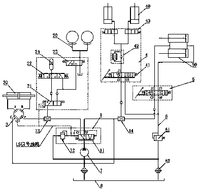
[0004] The purpose of the present invention is to solve the technical problems of complex and low-efficiency hydraulic drive systems of existing forklifts, provide a hydraulic drive system for forklifts, and improve the integration of hydraulic systems

Method used


Image

  • Hydraulic drive system for forklift

Examples


Embodiment 1

[0038] Such as figure 1 As shown, a hydraulic drive system for a forklift according to the present invention includes a braking device 20, a lifting cylinder 40, a tilting cylinder 50 and a steering cylinder 30, and the braking device 20, the lifting cylinder 40, and the tilting cylinder 50 and steering oil cylinder 30 provide high-pressure oil gear pump 7 and hydraulic oil tank 8; the drive system also includes oil inlet valve plate 1, brake oil circuit 2, steering oil circuit 3, lifting oil circuit 4, inclined oil circuit 5 and oil return line 6.

[0039] Specifically, a brief description of the above oil inlet valve plate 1, each functional oil circuit and oil return pipeline 6 is given as follows:

[0040] Oil inlet valve plate 1, which includes a priority valve 11, a safety valve 12, a first three-way flow limiting valve 13 and a second three-way flow limiting valve 14; the inlet of the priority valve 11 is connected to the outlet of the gear pump 7, and the hydraulic pr...

Embodiment 2

[0061] The structure of this embodiment 2 is the same as that of embodiment 1, and this embodiment 2 is to describe the brake oil circuit 2 in detail:

[0062] The brake system of the hydraulic drive system for forklifts in the second embodiment includes a brake device 20 and a brake oil circuit 2 . The brake device 20 is adapted to be hydraulically driven to brake the wheels of the forklift. refer to figure 1 As shown, the brake oil circuit 2 includes an accumulator 24, a first control valve 21, a second control valve 22, a third control valve 23, a first one-way valve and a second one-way valve.

[0063] Specifically, the first control valve 21 is respectively connected to the accumulator 24, the first three-way restrictor valve 13 and the braking device 20; the first control valve 21 is an electromagnetic reversing valve or a mechanical reversing valve, It can selectively output hydraulic oil to the accumulator 24 or the braking device 20 .

[0064] The first control val...


PUM


Abstract

The invention discloses a hydraulic drive system for a forklift. The hydraulic drive system is characterized by comprising a brake device, a lift cylinder, a tilt cylinder, a steering cylinder, and agear pump and a hydraulic oil tank for supplying high pressure oil to the brake device, the lift cylinder, the tilt cylinder, and the steering cylinder; The drive system further comprises an oil inletvalve plate, a brake oil passage, a steering oil passage, a lift oil passage, and a return oil pipeline. When the drive system is working, the hydraulic oil of the gear pump is divided into two pathsby a priority valve in the oil inlet valve plate. One path controls steering and braking of the forklift body through the brake oil passage and the steering oil passage; and the other path is connected with the lift oil passage and a tilt oil passage, and controls lifting action and tilting action of a portal frame. Compared with the conventional hydraulic drive system, the hydraulic drive systemfor the forklift disclosed by the invention has lower manufacturing cost, is lighter and comfortable to operate, and improves production efficiency.

Description

technical field [0001] The invention belongs to the technical field of forklift drive systems, and in particular relates to a hydraulic drive system for forklifts. Background technique [0002] Hydraulic transmission control is a flexible and convenient control method often used in the forklift manufacturing industry. It uses hydraulic pressure to complete the process of transferring energy. It uses pressurized fluid as the energy medium to realize automatic control of various machines. Hydraulic transmission uses components to form the various control circuits required, and then organically combines several circuits into a transmission system that completes certain control functions to complete energy transmission, conversion and control. [0003] At present, in the installation process of medium-tonnage forklifts, the traditional hydraulic system is usually used, which has the following characteristics: The traditional hydraulic system of this type of forklift is "hydra...

Claims


Application Information

Patent Timeline
Patent Type & Authority Applications(China)
IPC IPC(8): B66F9/075B66F9/22B60T13/14B62D5/07F15B1/02F15B11/16F15B13/06
Inventor 黄石坚
Owner 广州市广韬教学设备有限公司
Why Eureka
Eureka Blog
Learn More