
Ramming and groove digging mechanical device for building construction

A mechanical equipment and rammed earth technology, applied in the field of rammed earth trenching machinery and equipment, can solve the problems of low work efficiency, low efficiency, and difficult construction, and achieve the effects of saving manpower, material resources and financial resources, convenient operation, and easy construction.

Inactive Publication Date: 2018-12-21
成都市创斯德机电设备有限公司
View PDF0 Cites 3 Cited by
  • Summary
  • Abstract
  • Description
  • Claims
  • Application Information

AI Technical Summary

Problems solved by technology

[0003] Since the foundation beam frame is an indoor area, it will involve construction concrete, water and electricity pipes, and tile pasting after the house is built. Therefore, it is necessary to make the area inside the foundation beam frame lower than the foundation beam. Dig a groove 10 to 30 cm below the foundation beam, and then tamp the earthwork in the foundation frame to facilitate indoor construction later. At present, most of the excess earthwork is removed and trenches are excavated by excavators, and rammed earth is used for rammed earth machine, but the excavator is not easy to construct due to the shallow depth of the groove required when digging the groove, and it is more inconvenient to construct in small areas such as toilets and kitchens; The construction is also very inconvenient, and the efficiency is extremely low. If you encounter a small area, you can only rely on manual labor, which is labor-intensive and low-efficiency.

Method used


Image

  • Ramming and groove digging mechanical device for building construction
  • Ramming and groove digging mechanical device for building construction
  • Ramming and groove digging mechanical device for building construction

Examples


Embodiment Construction

[0021] All features disclosed in this specification, or steps in all methods or processes disclosed, may be combined in any manner, except for mutually exclusive features and / or steps.

[0022] Any feature disclosed in this specification, unless specifically stated, can be replaced by other alternative features that are equivalent or have similar purposes. That is, unless expressly stated otherwise, each feature is one example only of a series of equivalent or similar features.

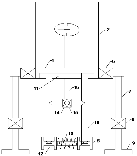
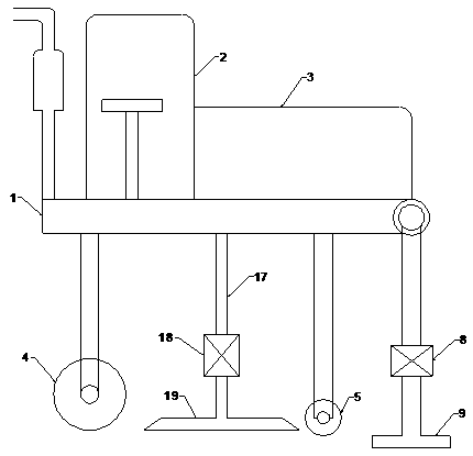
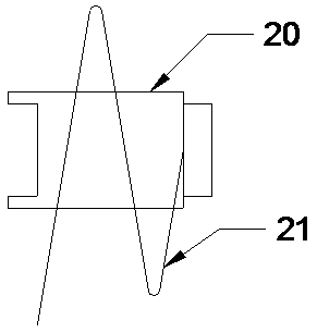
[0023] Such as Figure 1 to Figure 3 As shown, the present invention is a rammed earth digging mechanical equipment for house construction, including a chassis 1, a driver's cab 2 and a power room 3 arranged on the chassis 1, a driving wheel 4 and a driven wheel 5 arranged below the chassis 1 , the driven wheel 5 includes a left driven wheel and a right driven wheel, the driving wheel 4 and the driven wheel 5 are arranged in a triangle and the driven wheel 5 is in front of the driving wheel 4, and th...


PUM


Abstract

The invention discloses a ramming and groove digging mechanical device for building constructions. The device comprises a chassis, a cab room and a power room arranged on the chassis, and a driving wheel and driven wheels arranged below the chassis. Two sides of the chassis are respectively horizontally and fixedly connected with first hydraulic cylinders. Lifting columns are vertically arranged at an end part of piston rods of the first hydraulic cylinders. Second hydraulic cylinders are vertically and fixedly connected to lower ends of the lifting columns. Cylinder bodies of the second hydraulic cylinders are connected to the lifting columns. Ends of the piston rods are connected with ramming plates. A plurality of sequentially connected soil loosening structures is arranged horizontallybetween a left driven wheel and a right driven wheel. A groove digging structure assembly is arranged between the driving wheel and the driven wheels. According to the ramming and groove digging mechanical device for building construction, soil loosening and pushing grooves are performed in an area in a foundation beam frame at the same time in the walking process by taking the foundation beam asa track, and earth compaction is performed by using ramming plates at last, so that the effects of being easy to construct, quick and efficient, and capable of greatly saving manpower and material resources are achieved.

Description

technical field [0001] The invention relates to the field of construction engineering, in particular to a rammed-earth digging mechanical device used for house construction. Background technique [0002] Construction engineering refers to the engineering entity formed through the construction of various housing buildings and their ancillary facilities and the installation activities of supporting lines, pipelines and equipment. Among them, "housing construction" refers to projects that have roofs, beams, walls, foundations, and can form internal spaces to meet the needs of people's production, living, learning, and public activities. The brick-concrete structure will be used. When building a brick-concrete structure house, the foundation needs to be laid first. After the foundation is laid, the foundation beams are poured with steel bars and concrete on the foundation. , to ensure the stability of the house construction, and finally remove the excess earthwork, leaking the ...

Claims


Application Information

Patent Timeline
Patent Type & Authority Applications(China)
IPC IPC(8): E02F5/02E02F5/32E02D3/046
CPCE02F5/02E02D3/046E02F5/32
Inventor 高启新舒春柳
Owner 成都市创斯德机电设备有限公司
Learn More