
Underground spiral flow tubular column for separately exploiting gas and liquid and system analysis method

A gas flow and pipe string technology, which is applied in the field of downhole swirl gas-liquid separation production pipe string, can solve the problems of low lifting efficiency and the like

Active Publication Date: 2018-12-21
CHINA NAT OFFSHORE OIL CORP +1
View PDF10 Cites 9 Cited by
  • Summary
  • Abstract
  • Description
  • Claims
  • Application Information

AI Technical Summary

Problems solved by technology

[0005] The present invention aims to solve technical problems such as low lifting efficiency of conventional electric pump wells in offshore oil fields with high gas-liquid ratio oil wells, "air lock" and low lifting efficiency in severe cases, and provides a downhole swirling gas-liquid separation The pipe string and system analysis method, the process string has the characteristics of convenient construction and high work stability, the system analysis method has clear thinking, reliable calculation method, simple system coordination and control, and can be widely used in offshore high gas-liquid ratio oil wells Lifting process

Method used


Image

  • Underground spiral flow tubular column for separately exploiting gas and liquid and system analysis method
  • Underground spiral flow tubular column for separately exploiting gas and liquid and system analysis method
  • Underground spiral flow tubular column for separately exploiting gas and liquid and system analysis method

Examples


Embodiment Construction

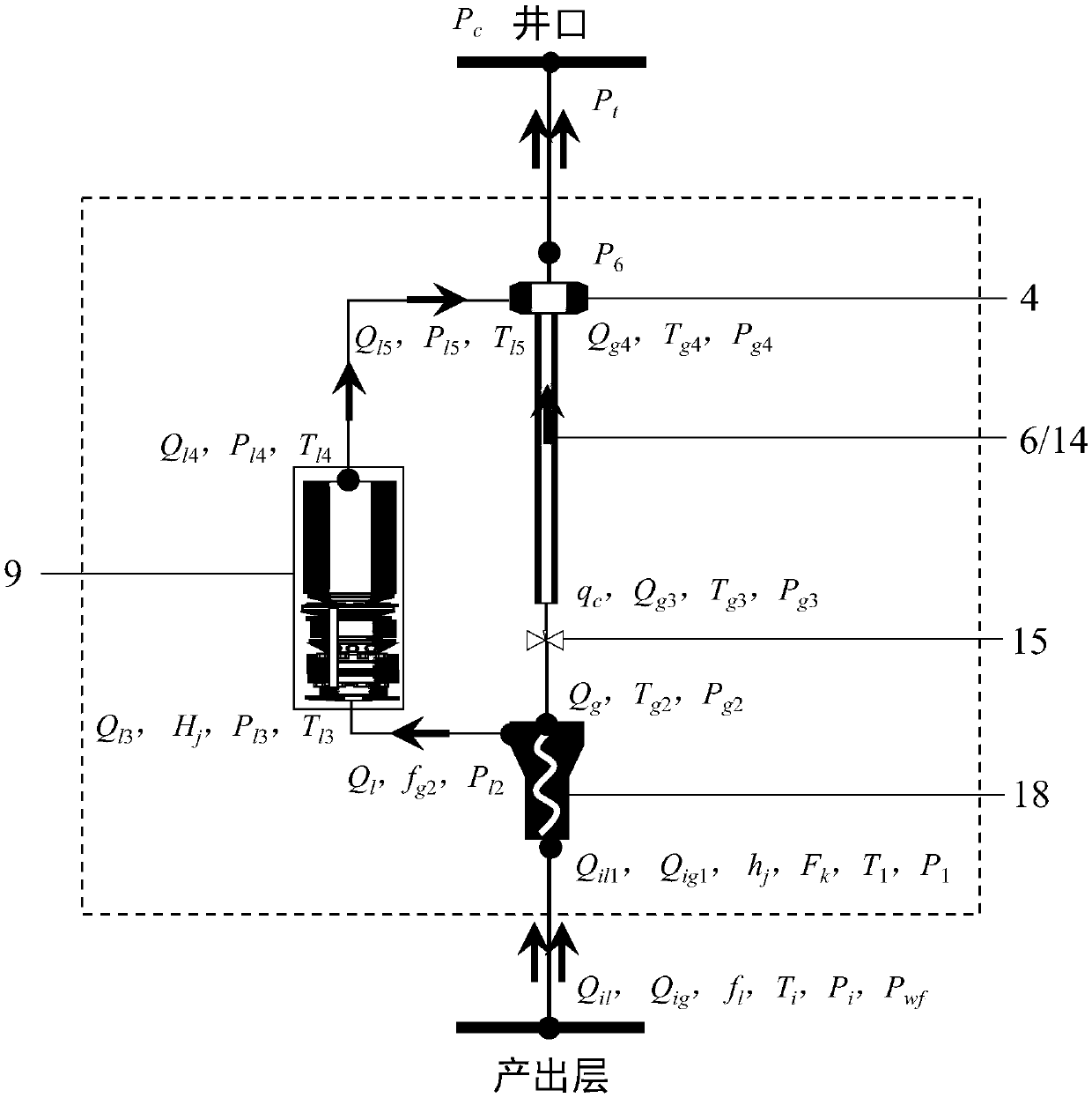
[0071] In order to further understand the invention content, characteristics and effects of the present invention, the following examples are given, and detailed descriptions are as follows in conjunction with the accompanying drawings:

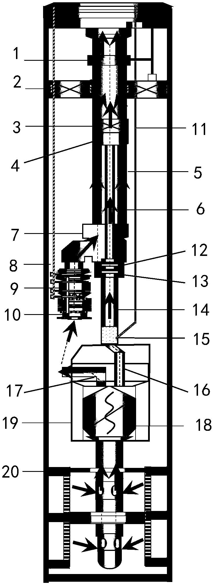
[0072] Such as figure 1 and figure 2 As shown, the present invention firstly provides a downhole swirling gas-liquid separate production string, which is set in the casing and includes a downhole safety valve 1, a cable packer 2, a velocity tubing hanger 3, a gas-liquid mixing Device 4, oil pipe 5, speed oil pipe 6, Y joint 7, power cable 8, electric pump unit 9, pump working condition 10, control cable 11, insertion seal 12, work cylinder 13, gas oil pipe 14, gas path adjustment device 15 , gas-liquid separation system 19 and top packer 20.

[0073] The lower part of the downhole safety valve 1 is connected to the velocity tubing hanger 3 through the tubing 5 . The wireline packer 2 is installed outside the tubing 5 between the downhole ...


PUM


Abstract

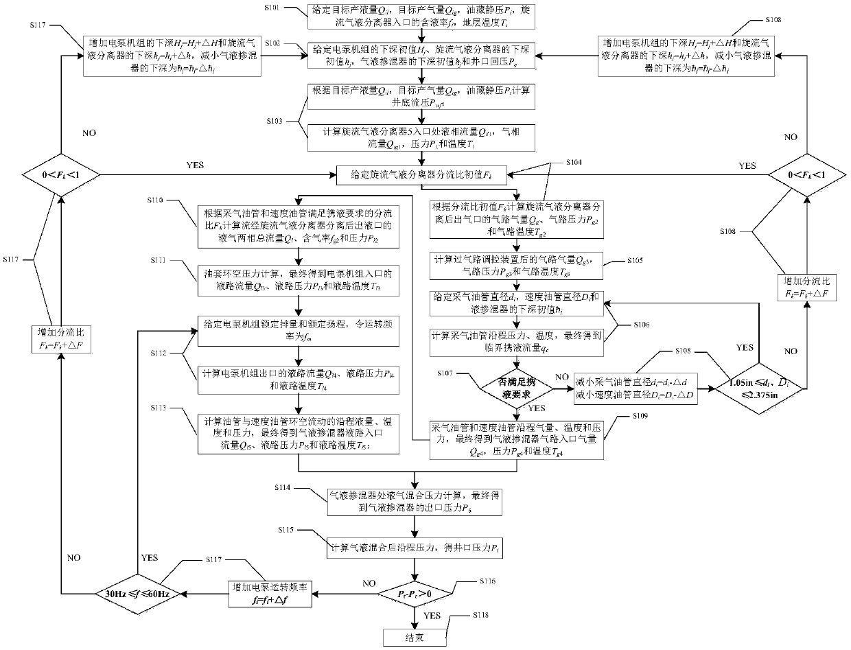
The invention belongs to the technical field of oilfield exploitation and discloses an underground spiral flow tubular column for separately exploiting gas and liquid and a system analysis method. Byutilizing a suspended speed oil tube in an oil tube, a gas-liquid lifting channel is built; by setting a split ratio, after gas and liquid flow through a spiral flow gas-liquid separator, the gas production amount and exit pressure of a gas-phase outlet and the liquid production amount, gas content rate and exit pressure of a liquid-phase outlet are calculated separately; pressure loss and critical liquid-gas loading amount after the gas passes through a gas nozzle are figured out through iterative computation to judge whether or not the speed oil tube meets the requirements for loading liquid. By setting electric pump feature parameters, pump discharge pressure and the annulus pressure loss of an on-way oil tube and the speed oil tube are figured out through the iterative computation until the pressure of an inlet of a gas-liquid mixing device is approachable to the pump discharge pressure; finally, the pressure loss between the on-way oil tube and a wellhead is figured out through the iterative computation until oil pressure is higher than flow backpressure. The technological tubular column has the advantages that convenience is provided for operation and construction, and the working stability is high. The system analysis method of the tubular column is clear in thinking pattern, reliable in computing approach and simple in system coordination control and can be widely applied to hoisting processes for marine oil wells with a high gas-liquid ratio.

Description

technical field [0001] The invention relates to the technical field of oilfield exploitation, in particular to a novel downhole swirling gas-liquid separate recovery pipe string and a system analysis method based on the pipe string. Background technique [0002] Offshore oilfields with high gas-liquid ratio oil wells (gas content > 60%) face problems such as low lifting efficiency of conventional electric pump wells, and in severe cases, "gas lock", which seriously affects the normal production of oil wells. At present, there are three commonly used lifting methods for oil wells with high gas-liquid ratio in offshore oilfields: 1) The conventional gas-liquid separator is suitable for well conditions where the gas content at the pump suction inlet is less than 30%; 2) The gas separation master can handle the pump suction inlet When the gas content is 30%-50%, the separation efficiency drops significantly when the gas content increases. 3) The gas processor compresses the ...

Claims


Application Information

Patent Timeline
IPC IPC(8): E21B43/00E21B43/38G06F17/50G06Q50/02
CPCE21B43/122E21B43/128E21B43/38G06Q50/02G06F30/20
Inventor 郑春峰杨万有刘敏沈琼程心平张凤辉赵景辉李昂薛德栋谢双喜
Owner CHINA NAT OFFSHORE OIL CORP
Learn More