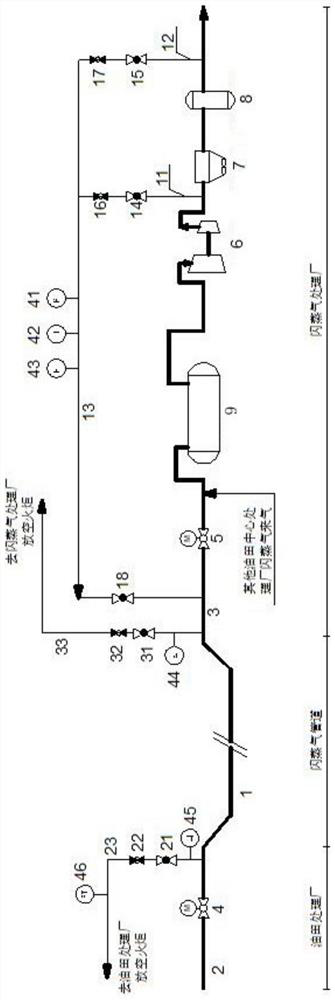
Oil field low-pressure flash steam pipeline conveying stopping accumulated liquid control system and method

A control system and flash gas technology, applied in the pipeline system, gas/liquid distribution and storage, chemical instruments and methods, etc., can solve economic losses, affect pipeline start-up, increase and other problems, achieve good economy and reduce size , reduce the effect of pipeline effusion

Pending Publication Date: 2021-01-05
BC P INC CHINA NAT PETROLEUM CORP +1
View PDF0 Cites 2 Cited by
  • Summary
  • Abstract
  • Description
  • Claims
  • Application Information

AI Technical Summary

Problems solved by technology

For oil field flash gas pipelines, if the pipeline is shut down when the ambient temperature is low, the temperature of the medium in the pipeline will quickly become consistent with the surrounding environment due to heat exchange, and most of the heavy hydrocarbons in the medium will be liquefied at this time. As a result, the liquid accumulation in the pipeline will further increase, which will increase the receiving load of the downstream slug flow catcher and affect the next restart of the pipeline
Although it can be solved by prolonging the operation time of pipeline recommissioning, this will directly affect the speed of resumption of production and cause certain economic losses
Yet prior art does not yet relate to special measure and scheme in this respect

Method used


Image

  • Oil field low-pressure flash steam pipeline conveying stopping accumulated liquid control system and method

Examples


Embodiment Construction

[0045] In order to make the purpose, technical solutions and advantages of the embodiments of the present invention clearer, the technical solutions in the embodiments of the present invention will be clearly and completely described below in conjunction with the drawings in the embodiments of the present invention. Obviously, the described embodiments It is a part of embodiments of the present invention, but not all embodiments. The components of the embodiments of the invention generally described and illustrated in the figures herein may be arranged and designed in a variety of different configurations.

[0046] Accordingly, the following detailed description of the embodiments of the invention provided in the accompanying drawings is not intended to limit the scope of the claimed invention, but merely represents selected embodiments of the invention. Based on the embodiments of the present invention, all other embodiments obtained by persons of ordinary skill in the art wi...


PUM


Abstract

The invention discloses an oil field low-pressure flash steam pipeline conveying stopping accumulated liquid control system and method. The system comprises a high-temperature gas reverse purging system, an upstream auxiliary pressure relief system, a flash steam treatment plant rapid relief system and a matched detection system. The high-temperature gas reverse purging system is used for providing high-temperature gas for a stopped flash steam main line, gasifying accumulated liquid in a pipeline and replacing a medium in the pipeline; the upstream auxiliary pressure relief system is used forreleasing flash steam in the reverse purging process of the flash steam pipeline after stopping conveying; the flash steam treatment plant rapid relief system is used for quickly releasing the mediumin the flash steam pipeline after stopping conveying or the flash steam pipeline directly releases when a treatment plant does not have reverse purge gas supply; and the matched detection system is used for detecting the temperature, the pressure and the flow of a required position in the system so as to provide an operation input signal and an input parameter. According to the system and the method, the accumulated liquid of the flash steam pipeline can be essentially and effectively controlled, and the influence on the restarting process is reduced.

Description

technical field [0001] The invention belongs to the technical field of pipeline transportation of oilfield flash steam, and in particular relates to a system and method for controlling liquid accumulation in low-pressure flash steam pipelines of oilfields. Background technique [0002] In the process of crude oil processing in the oilfield central processing plant, in order to ensure the quality of oil products, it is necessary to control the saturated vapor pressure and separate more flash gas from it, which is usually directly vented. With the increasing demand for energy saving, emission reduction and rational utilization of resources, the recovery and reuse of flash gas is advocated. Flash gas is a better oilfield fuel gas, which can be collected and processed for use by various public facilities in the oilfield. The flash gas contains more C1-C5 components, and its specific composition is affected by the crude oil stabilization process, and the dew point temperature is...

Claims


Application Information

Patent Timeline
Patent Type & Authority Applications(China)
IPC IPC(8): F17D1/02F17D1/04F17D1/065F17D3/01F17D3/18F16L55/07B08B9/032
CPCB08B9/0325B08B9/0328F16L55/07F17D1/02F17D1/04F17D1/065F17D3/01F17D3/18
Inventor 陈俊文乔靖杰龙增兵汤晓勇陈庆李娜代万春郑春来汪贵
Owner BC P INC CHINA NAT PETROLEUM CORP
Why Eureka
Try Eureka