Method for measuring wind tunnel density field based on video and sub-pixel technology

A density field and sub-pixel technology, applied in the direction of measuring devices, machine/structural component testing, instruments, etc., can solve problems such as complex installation, expensive interference system, complex post-processing algorithm, etc., to improve positioning accuracy and simplify test layout Effect

Inactive Publication Date: 2018-12-21
INST OF HIGH SPEED AERODYNAMICS OF CHINA AERODYNAMICS RES & DEV CENT
View PDF3 Cites 6 Cited by
  • Summary
  • Abstract
  • Description
  • Claims
  • Application Information

AI Technical Summary

Problems solved by technology

Interferometry records the phase difference of light waves, which reflects the refractive index itself. Interferometric systems are usually sensitive to environmental vibrations, and the installation is complicated. It can provide quantitative information, but the cost is high, and only small objects can be measured.
The schlieren method and the shadow method can generally only do qualitative research such as observing the change law of the density field, and cannot provide quantitative data
The interferometry technology based on phase change is an important aero-optical measurement technology. According to the interferometry results, the aero-optic performance parameters of the flow can be extracted, but the interferometry system used for high-resolution measurement is very expensive and is easily subject to environmental interference. Complex processing algorithm
[0003] Therefore, the current density field measurement technology is applied to the wind tunnel density field measurement, which is far from meeting the accuracy and calculation speed requirements of the measurement.

Method used


Image

  • Method for measuring wind tunnel density field based on video and sub-pixel technology
  • Method for measuring wind tunnel density field based on video and sub-pixel technology
  • Method for measuring wind tunnel density field based on video and sub-pixel technology

Examples


Embodiment Construction

[0046] The present invention will be further described in detail below in conjunction with the accompanying drawings, so that those skilled in the art can implement it with reference to the description.

[0047] It should be understood that terms such as "having", "comprising" and "including" as used herein do not entail the presence or addition of one or more other elements or combinations thereof.

[0048] An implementation form of a method for measuring a wind tunnel density field based on video and sub-pixel technology according to the present invention, including:

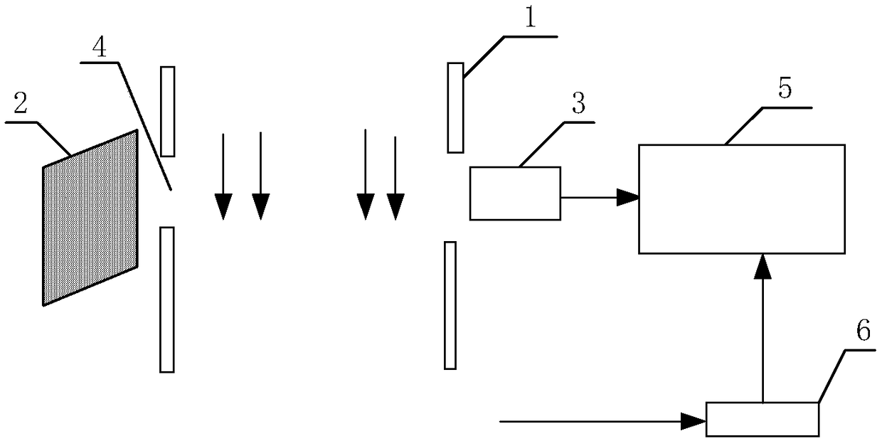
[0049] S1. Collect images of the density field before and during the wind tunnel test respectively to obtain corresponding static density field measurement images and dynamic density field measurement images. The present invention is based on video measurement, through comparison test process and test The position of the center of the foreground and background images is changed to calculate the optical refractiv...


PUM


Abstract

The invention discloses a method for measuring a wind tunnel density field based on video and a sub-pixel technology, which includes: S1, carrying out image acquisition on a density field before and during a wind tunnel test respectively to obtain corresponding static density field measurement images and dynamic density field measurement images; S2, locating centers of circles in the dynamic density field measurement images based on a sub-pixel positioning technology; and S3, calculating an optical refractive index with position change of coordinates of the centers of circles in the dynamic density field measurement images and coordinates of the centers of circles in the static density field measurement images so as to calculate and obtain a wind tunnel density field. The method provided by the invention is able to calculate the wind tunnel density field by comparing the position change of the centers of circles in background images during and before the test based on video measurement. Compared with the prior art, the method has the advantages of being simpler and more convenient, high precision and fast measuring speed.

Description

technical field [0001] The invention relates to a method used in the case of measuring performance indicators during testing. More specifically, the present invention relates to a method for measuring the density field of a wind tunnel in a wind tunnel test situation based on video and sub-pixel technology. Background technique [0002] At present, the technologies used for density field measurement mainly include three technical methods: schlieren method, shadow method, and interferometry. The shadow method records the deflection position difference, which reflects the change of the refractive index gradient, that is, the second derivative of the refractive index. The shadow method is often used in places where the density gradient changes greatly, suitable for large scales, and relatively low material requirements. Lowest cost. The Schlieren method records the deflection angle difference, which reflects the gradient of the refractive index, that is, the first derivative ...

Claims


Application Information

Patent Timeline
Patent Type & Authority Applications(China)
IPC IPC(8): G01M9/02
CPCG01M9/02
Inventor 唐亮周润洪兴福范金磊秦建华蒋鸿杨振华杨国超
Owner INST OF HIGH SPEED AERODYNAMICS OF CHINA AERODYNAMICS RES & DEV CENT
Why Eureka
Try Eureka