Lamp panel hardness detection device for LED illumination lamp production

A technology of LED lighting and testing device, applied in the direction of measuring device, testing material hardness, strength characteristics, etc., can solve problems such as affecting the overall performance and quality of the product, short circuit of the LED lamp board power supply, inaccurate test data, etc., to improve the test Effectiveness of efficiency and test quality, increased stability and security, increased flexibility

Inactive Publication Date: 2018-12-21
张玉锦
View PDF1 Cites 0 Cited by
  • Summary
  • Abstract
  • Description
  • Claims
  • Application Information

AI Technical Summary

Problems solved by technology

[0002] At present, most LED lamps are made of aluminum substrates with SMT technology. LEDs are welded on the circuit surface of the aluminum substrates, and the aluminum substrates are connected by multiple boards. Since the LED lamps, circuits and solder pads are on the same circuit layer, the production line will be damaged after LED welding. When the light and point tests are performed on the light board, it is necessary to supply power to the power supply of each light board separately for light and electrical testing. However, the test efficiency is low during operation, and it is very easy to cause a short circuit of the power supply of the LED light board when manually connecting the power line. LED scratches, poor contact, etc., cause material damage and inaccurate test data, thus affecting the overall performance and quality of the product
[0003] In the process of production, when testing LED light panels, because the existing technology lacks related equipment designed specifically for this test, the detection efficiency is very low, and the column LED lights cannot be fixed well. It is not convenient to detect the board

Method used


Image

  • Lamp panel hardness detection device for LED illumination lamp production
  • Lamp panel hardness detection device for LED illumination lamp production
  • Lamp panel hardness detection device for LED illumination lamp production

Examples


Embodiment Construction

[0021] The following will clearly and completely describe the technical solutions in the embodiments of the present invention with reference to the accompanying drawings in the embodiments of the present invention. Obviously, the described embodiments are only some, not all, embodiments of the present invention.

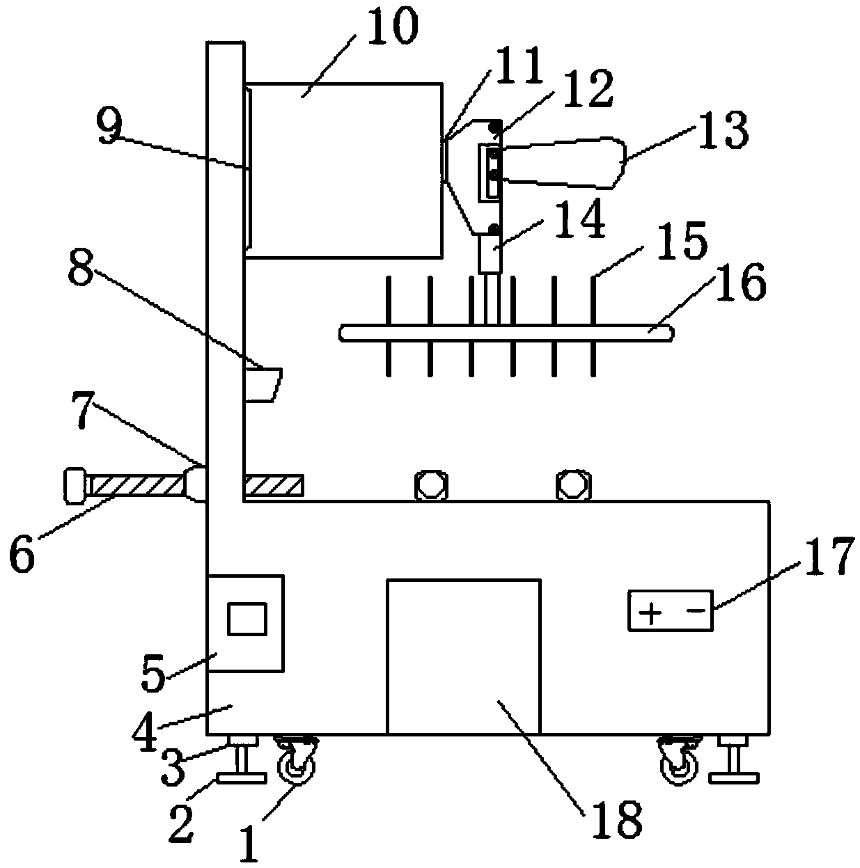
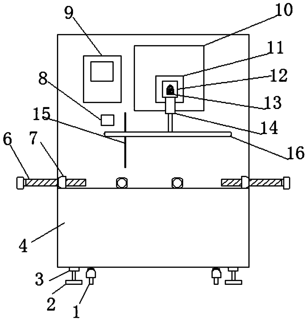
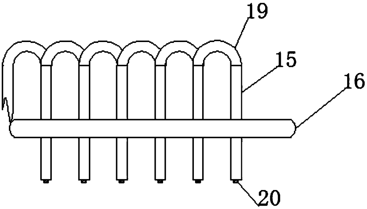
[0022] refer to Figure 1-3 , a light board hardness testing device for LED lighting production, including an L-shaped test platform 4, including an L-shaped test platform 4, the outer wall of the bottom of the L-shaped test platform 4 is fixed with a hydraulic cylinder 3 by screws, and the hydraulic cylinder 3 The top of the extension rod is fixed with a support block 2 by screws, the outer wall of the bottom end of the L-shaped test platform 4 near the hydraulic cylinder 3 is fixed with a universal wheel 1 by screws, and there is a cavity in the L-shaped test platform 4. And the inner wall of one side of the L-shaped test carrier 4 is fixed with a processor 5 by sc...


PUM


Abstract

The invention discloses a lamp panel hardness detection device for LED illumination lamp production. The lamp panel hardness detection device comprises an L-shaped test carrier table; hydraulic cylinders are fixed to the outer wall of the bottom of the L-shaped test carrier table through screws; supporting blocks are fixed at the top ends of extension rods of the hydraulic cylinders through screws; universal wheels are fixed to the outer wall of the bottom end of one side, close to the hydraulic cylinders, of the L-shaped test carrier table through screws; a cavity is formed in the L-shaped test carrier table; a processor is fixed on the inner wall of one side of the L-shaped test carrier table through screws; a storage battery is fixed on the inner wall of the bottom of the L-shaped testcarrier table through screws; a power switch is fixed on the outer wall of one side of the L-shaped test carrier table through screws; a first through hole is formed in the outer wall of one side, close to the processor, of the L-shaped test carrier table; and a lamp panel positioning screw rod is inserted into the first through hole. The device can be flexibly stretched and matched with a test needle fixing plate; and an LED lamp panel is accurately connected with a test power supply, so that the stability and safety of the device are improved.

Description

technical field [0001] The invention relates to the technical field of lamp board hardware detection devices, in particular to a lamp board hardness detection device for LED lighting production. Background technique [0002] At present, most LED lamps are made of aluminum substrates with SMT technology. LEDs are welded on the circuit surface of the aluminum substrates, and the aluminum substrates are connected by multiple boards. Since the LED lamps, circuits and solder pads are on the same circuit layer, the production line will be damaged after LED welding. When the light and point tests are performed on the light board, it is necessary to supply power to the power supply of each light board separately for light and electrical testing. However, the test efficiency is low during operation, and it is very easy to cause a short circuit of the power supply of the LED light board when manually connecting the power line. LED scratches, poor contact, etc., cause material damage a...

Claims


Application Information

Patent Timeline
Patent Type & Authority Applications(China)
IPC IPC(8): G01N3/40
CPCG01N3/40G01N2203/0076G01N2203/0282
Inventor 张玉锦
Owner 张玉锦
Why Eureka
Try Eureka