
Apparatus and method for picking-up and placing reaction cup and equipment comprising apparatus

A technology of reaction cups and cup stems, which is applied in the direction of analysis, instruments, chemiluminescence/bioluminescence, etc. by making materials undergo chemical reactions, which can solve the problems of increasing equipment maintenance costs, component failure, frequent maintenance, etc., and achieve guaranteed detection Accuracy and detection efficiency, reduced maintenance costs, and the effect of avoiding empty grabbing

Pending Publication Date: 2018-12-21
SUZHOU SYM BIO LIFESCI CO LTD
View PDF2 Cites 3 Cited by
  • Summary
  • Abstract
  • Description
  • Claims
  • Application Information

AI Technical Summary

Problems solved by technology

[0003] However, there are various cuvette grippers in the prior art, for example: European Patent EP2462455A1 discloses a gripper device, which is provided with a first movable jaw and a second movable jaw arranged along the side of the gripper; The first finger and the second finger are respectively coupled to the first movable jaw and the second movable jaw for grasping the sample container, but in the gripper device described in the patent The gripping jaws are continuously opened and closed by the corresponding driving device to realize the grabbing of the sample container. Its structure is very complex, and there are many moving parts, which are easy to be damaged and frequently maintained, which will increase the maintenance cost of the equipment. And affect the efficiency of grabbing cups; European patent EP1355766B1 discloses a clamping assembly for taking and placing containers, which includes a gripper arranged at the bottom end of a cylinder, and a piston that slides relative to the interior of the cylinder, which relies on the grasping The elastic deformation of the hand grabs the container and pushes the container out of the handle through the downward movement of the piston to release the cuvette. Although the structure of the clamping assembly is relatively simple, the release position of the container must be higher than the placement position of the container, which will The container will fall a certain height, which will easily cause the liquid in the container to splash, thus seriously affecting the detection accuracy of the sample. Moreover, the gripper involved in this patent is one of the parts of the clamping assembly, which may be damaged due to many Fatigue failure due to secondary deformation, which leads to the failure of the entire component, also has the problems of easy damage, increased equipment maintenance costs, and reduced detection efficiency

Method used


Image

  • Apparatus and method for picking-up and placing reaction cup and equipment comprising apparatus
  • Apparatus and method for picking-up and placing reaction cup and equipment comprising apparatus
  • Apparatus and method for picking-up and placing reaction cup and equipment comprising apparatus

Examples


Embodiment 1

[0064] This embodiment is a preferred device for picking and placing cuvettes.

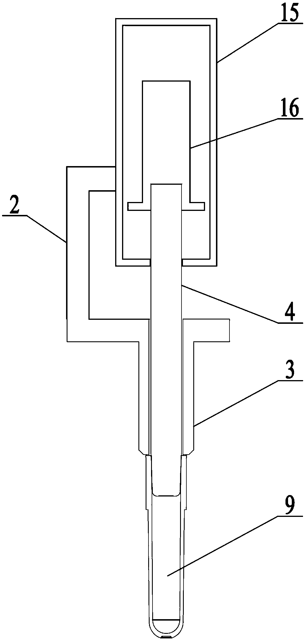
[0065] Such as figure 1 As shown, the device for picking and placing cuvettes described in this embodiment includes a pick-up mechanism, a movement mechanism, a cup removal mechanism, a drive mechanism and a housing, wherein the pick-up mechanism includes a cup-taking lever 4, and the movement mechanism includes a piston 16 , The cup removal mechanism includes a sleeve 3, and the driving mechanism includes a cylinder 15.

[0066] In this embodiment, when the cuvette 9 is picked up, the inner wall of the cuvette 9 is in contact with the outer wall of the stem 4, and is maintained by the friction force between the two. The inner diameter of the cuvette is slightly smaller than the outer diameter of the end of the stem 4. (such as small 0.1mm, 0.2mm, 0.25mm, 0.3mm, 0.4mm, etc.), and the bottom of the cup stem 4 is an inverted arc structure, which is beneficial to the upper opening of the embedded cu...

Embodiment 2

[0071] This embodiment is an optimized implementation of the device for picking up and placing cuvettes described in Embodiment 1. Its main optimization points are that different drive mechanisms and motion mechanisms are provided, and the connection mode of the cup stem and the connection of the sleeve way, as well as the use of different shell forms, and the addition of a vent hole for the cup stem, the specific improvements are as follows:

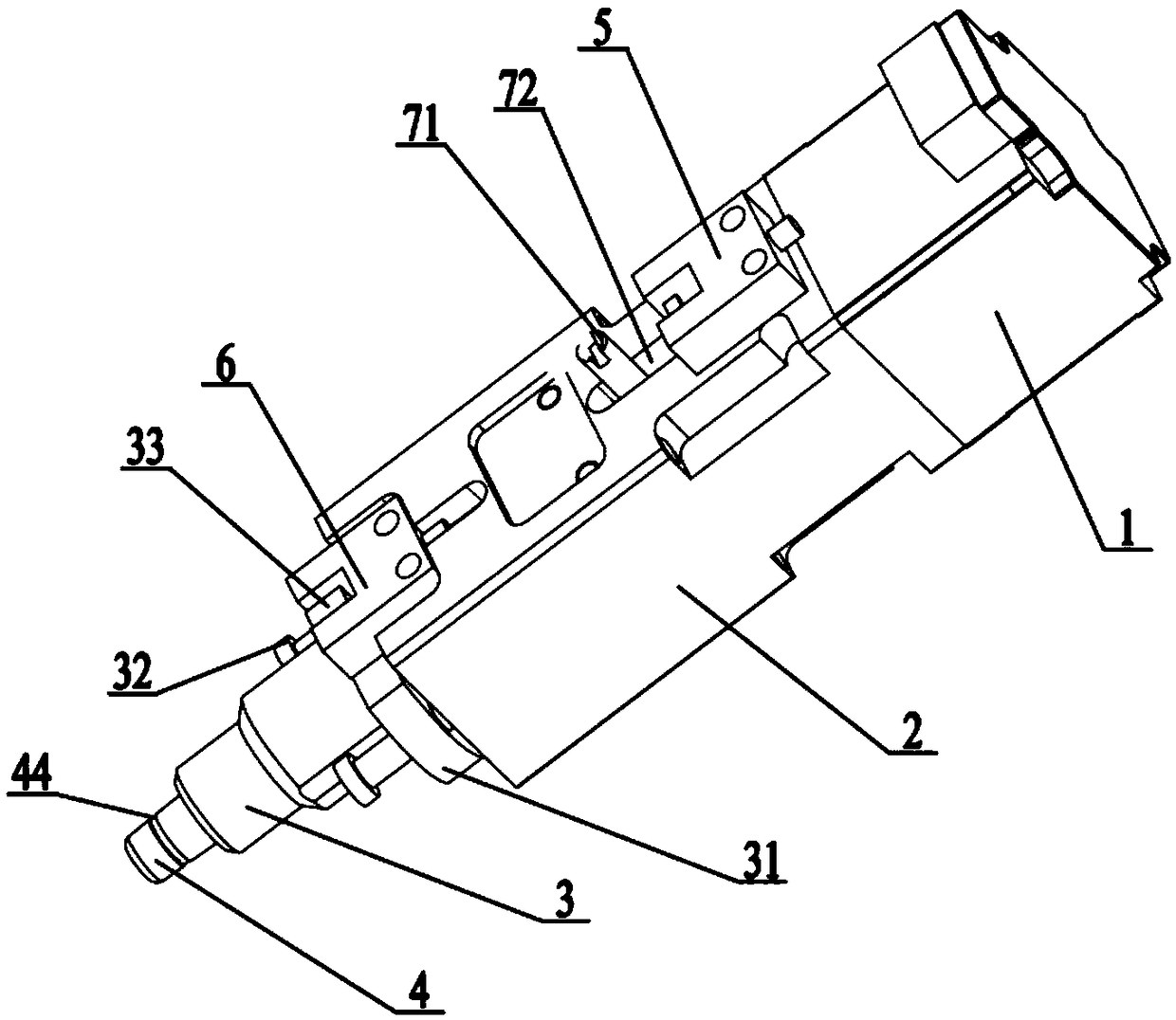
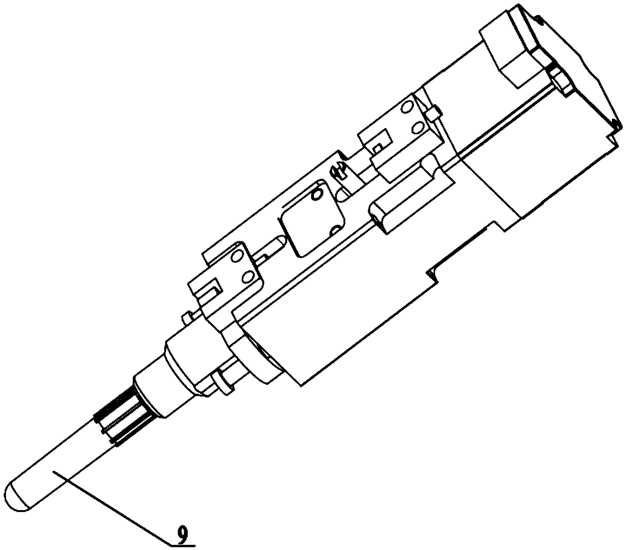
[0072] Such as Figure 2 to Figure 5 As shown, the movement mechanism in the device for picking and placing cuvettes described in this embodiment includes a nut 7 , and the driving mechanism includes a motor 1 .

[0073] In this embodiment, the cup stem 4 is integrally fixed to the bottom of the cup stem connector 41; the nut 7 is fixed to the top of the cup stem connector 41 by screw connection; the top end of the sleeve 3 is It is integrally formed on the bottom of the sleeve mounting plate 31. The bottom end of the sleeve 3 is used ...

Embodiment 3

[0078] This embodiment is an optimized implementation of the device for picking and placing cuvettes described in the second embodiment. The main optimization point is to set up a detector for detecting the position of the sleeve and the nut, and adopt different forms of cuvettes and drive mechanisms, and optimize the installation form of the sleeve. The specific improvements are as follows:

[0079] In this example, if Figure 2 to Figure 5As shown, the screw rod 11 is sleeved with a screw limiting groove 12, and the screw limiting groove 12 is opened in the cup-taking rod connector 41, so as to prevent the screw rod 11 from driving the nut 7 to move downwards excessively and damage the device; and The side end of nut 7 is equipped with nut stopper bar 71, and housing 2 offers nut stopper groove 72, and nut stopper bar 71 extends through described nut stopper groove 72, and is positioned at the casing 2 of nut stopper groove 72 tops. The first sensor 5 is installed externall...


PUM


Abstract

The invention provides an apparatus for picking-up and placing a reaction cup. The apparatus for picking-up and placing the reaction cup comprises a picking-up mechanism, a moving mechanism, a cup removing mechanism and a driving mechanism. The picking-up mechanism is in contact with the inner wall of the reaction cup for picking up the reaction cup. The moving mechanism is fixedly connected withthe picking-up mechanism so as to drive the picking-up mechanism to move. The cup removing mechanism is arranged on the outer side of the picking-up mechanism in a sleeving mode and fixedly installedon a shell body. The picking-up mechanism moves relative to the reaction cup, and the placement of the reaction cup is realized. The driving mechanism is fixedly installed on the shell body, and is connected to the moving mechanism so as to drive the moving mechanism. The invention further relates to a method for picking-up and placing the reaction cup and equipment comprising the apparatus for picking-up and placing the reaction cup. The apparatus for picking-up and placing the reaction cup relies on the deformation of the reaction cup to generate frictional force, the problem of loss of thereaction cup picking apparatus does not exist, thus, the service life of the reaction cup picking apparatus is ensured, and maintenance cost of the equipment is reduced. The reaction cup picking scheme is that a reaction cup picking rod actively exits from the reaction cup, the risk of liquid spilling from the reaction cup is avoided, and thus the detection accuracy and detection efficiency are ensured.

Description

technical field [0001] The invention relates to the technical field of biochemical analysis devices, in particular to a device and method for picking up and releasing a cuvette and equipment containing the device. Background technique [0002] At present, the automation of biological and chemical analysis devices is becoming more and more common, which can realize the continuous automatic detection of multiple reaction cups. During the experimental detection process, the reaction cups need to be transferred in different functional areas, which means that the reaction cups Reliable pick and place is very important. In current analysis devices, it is generally necessary to configure multiple cuvette grippers to realize the transfer of cuvettes in different functional areas. [0003] However, there are various cuvette grippers in the prior art, for example: European Patent EP2462455A1 discloses a gripper device, which is provided with a first movable jaw and a second movable j...

Claims


Application Information

Patent Timeline
IPC IPC(8): G01N35/00G01N35/10G01N21/76
CPCG01N35/00G01N21/76G01N35/10
Inventor 许明
Owner SUZHOU SYM BIO LIFESCI CO LTD
Learn More