
Bayesian iterative reweighted sparse autofocus array SAR imaging method

A Bayesian and self-focusing technology, applied in the direction of radio wave reflection/re-radiation, using re-radiation, measurement devices, etc., can solve problems such as less consideration of measurement matrix errors or uncertain effects

Active Publication Date: 2018-12-21
UNIV OF ELECTRONICS SCI & TECH OF CHINA
View PDF6 Cites 17 Cited by
  • Summary
  • Abstract
  • Description
  • Claims
  • Application Information

AI Technical Summary

Problems solved by technology

However, most current CS sparse imaging algorithms rarely consider the effects of errors or uncertainties in the measurement matrix

Method used


Image

  • Bayesian iterative reweighted sparse autofocus array SAR imaging method
  • Bayesian iterative reweighted sparse autofocus array SAR imaging method
  • Bayesian iterative reweighted sparse autofocus array SAR imaging method

Examples


Embodiment Construction

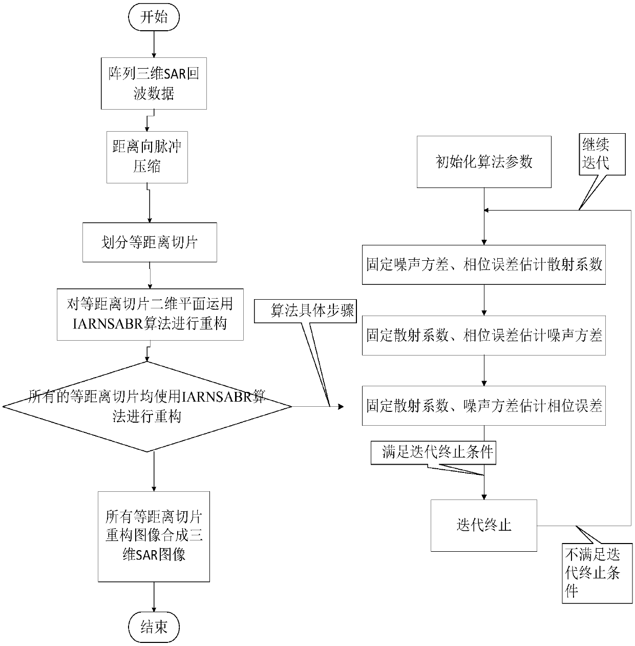
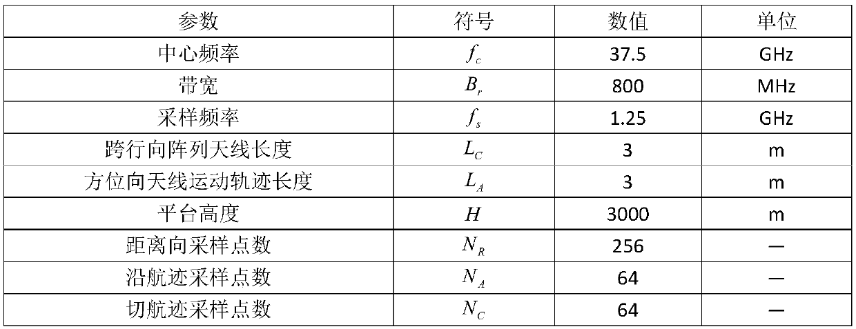
[0075] The present invention mainly adopts the method of computer simulation to verify, and all steps and conclusions are verified correctly on MATLAB-2017b. The specific implementation steps are as follows:

[0076] Step 1. Initialize SAR system parameters:

[0077] The initial SAR system parameters include: the platform velocity vector is recorded as The initial position vector of each element of the array antenna, denoted as n=1,2,...,N, where n is the serial number of each element of the antenna, N=64 is the total number of elements of the array antenna; the length of the array antenna is recorded as L=3m; the carrier frequency of the radar transmitting signal is f c =37.5GHz; the frequency modulation slope of the radar transmitted signal is f dr =4×10 14 Hz / s; the pulse repetition time is recorded as PRI=2μs; the pulse repetition frequency of the radar system is PRF=0.5MHz; the radar transmission signal bandwidth is recorded as B r =0.8GHz; the propagation speed of...


PUM


Abstract

The invention discloses a Bayesian iterative reweighted sparse autofocus array synthetic aperture radar (SAR) imaging method. The Bayesian iterative reweighted sparse autofocus array SAR imaging method aims at the influence of phase errors existing in array SAR echo signals on imaging results. Based on a traditional sparse autofocus Bayesian recovery via iterative minimum (SAFBRIM) algorithm, a linear measurement matrix of scattering coefficients in the array SAR original echo signals and an observation scene target space is established, norm items in a cost function in the algorithm are subjected to iterative adaptive reweighted processing, pulse compression and equidistant surface division are carried out on a distance direction, and then each equidistant two-dimensional surface is estimated. According to the Bayesian iterative reweighted sparse autofocus array synthetic aperture radar (SAR) imaging method, different weighting coefficients are given to each norm item, and then imagesare reconstructed, so that higher-quality array SAR imaging results can be obtained. The Bayesian iterative reweighted sparse autofocus array synthetic aperture radar (SAR) imaging method has the advantages of high reconstruction precision and effective reduction of phase errors, and can be applied to the fields such as array synthetic aperture radar imaging.

Description

technical field [0001] The invention belongs to the technical field of radar, in particular to the technical field of synthetic aperture radar (SAR) imaging. Background technique [0002] As an active radar operating in the microwave band, Synthetic Aperture Radar (SAR) has all-weather and all-weather imaging capabilities, that is, it can image anytime, anywhere, whether it is day or night, sunny or thunderstorm. , to overcome the shortcomings of optical and infrared systems that cannot be imaged at night and in complex weather conditions. Traditional SAR imaging generally only has two-dimensional imaging resolution. In places with relatively large ups and downs, such as steep peaks, canyons, and tall buildings in cities, the distortion (shadow occlusion effect, spatial blur, roof, etc.) of traditional SAR imaging exists. Bottom inversion, etc.) lead to the loss of some important information in space (such as height), so it is very necessary to be able to perform three-dime...

Claims


Application Information

Patent Timeline
IPC IPC(8): G01S13/90G01S7/41
CPCG01S7/41G01S13/90G01S13/9004
Inventor 张晓玲田博坤党丽薇范昕玥闫敏韦顺军师君
Owner UNIV OF ELECTRONICS SCI & TECH OF CHINA
Learn More