Train velocity curve tracking control method and system based on event triggering PID control

A tracking control and speed curve technology, which is applied in general control systems, control/regulation systems, adaptive control, etc., can solve the problem of reducing the real-time performance and accuracy of control, cannot be applied, and cannot guarantee that the minimum interval between event triggers is greater than or equal to the sensor Lower limit and other issues to achieve the effect of reducing the number of calculations and burden, reducing the failure rate, and improving the service life

Active Publication Date: 2018-12-21
BEIJING JIAOTONG UNIV
View PDF5 Cites 14 Cited by
  • Summary
  • Abstract
  • Description
  • Claims
  • Application Information

AI Technical Summary

Problems solved by technology

[0004] Most of the event triggers mentioned by scholars in the past stay in theory, by proving that there is a lower limit for the interval of event triggers, in order to avoid the Zeno phenomenon (in event trigger control, if the time interval between any two adjacent triggers is very short, it may cause triggering of infinitely many events), however, there is a lower limit on the sampling interval of the sensor during the actual train operation, and there is no guarantee that the minimum interval of event triggering is greater than or equal to the lower limit of the sensor, and if the triggering interval of two adjacent events is not the lower limit of the sensor sampling interval Integer multiples, the sensor cannot transmit the train status information to the train controller in time, which will greatly reduce the real-time and accuracy of the control, so the relevant theory cannot be applied to the actual train operation control process

Method used


Image

  • Train velocity curve tracking control method and system based on event triggering PID control
  • Train velocity curve tracking control method and system based on event triggering PID control
  • Train velocity curve tracking control method and system based on event triggering PID control

Examples


Embodiment 1

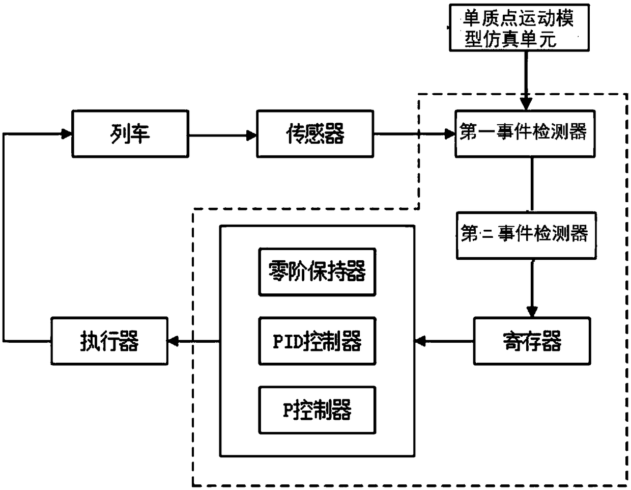
[0058] Such as figure 1 The illustrated embodiment of the present invention provides a train speed curve tracking control system based on event-triggered PID control, the system comprising:

[0059] A single-mass motion model simulation unit is used to establish a single-mass motion simulation model in which the basic resistance is zero when the train starts;

[0060] The sensor group is used to collect the actual running state of the train;

[0061] The first event detector obtains the motion state difference between the actual running state and the expected motion state in the single-mass motion simulation model, and judges whether the motion state difference satisfies the trigger control update condition, and if so, updates the The motion state difference value is sent to the second event detector;

[0062] A second event detector, configured to determine whether to trigger a control state update according to the absolute value of the motion state difference and the rate ...

Embodiment 2

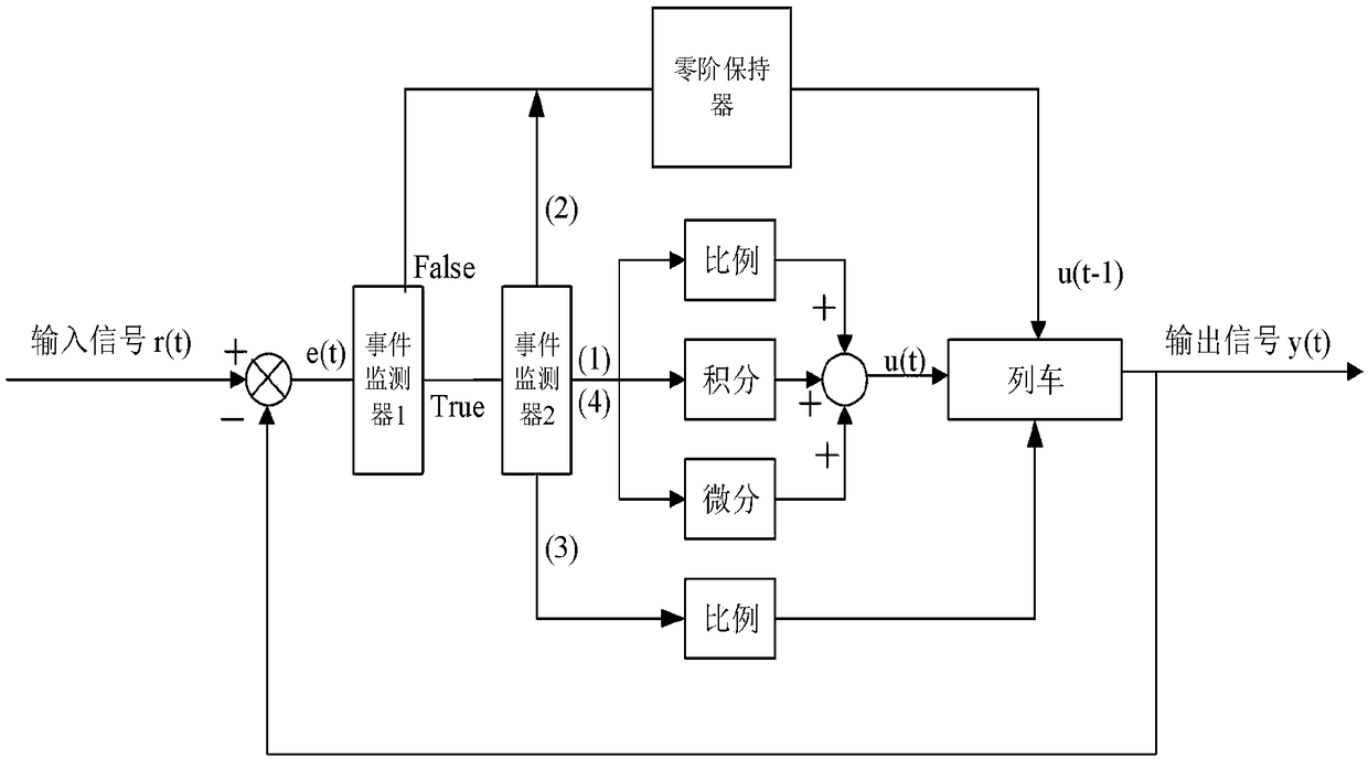
[0080] Such as figure 2 As shown, a kind of train speed curve tracking control method based on time-triggered PID control provided by Embodiment 2 of the present invention includes the following steps:

[0081] Step S110: establishing a single-mass motion simulation model in which the basic resistance is zero when the train starts;

[0082] Step S120: Collect the actual motion state of the train, and obtain the motion state difference according to the expected motion state corresponding to the sampling time point in the single-mass motion simulation model;

[0083] Step S130: Judging whether the motion state difference satisfies the trigger control update condition, if so, proceed to step S130, otherwise, maintain the original control state;

[0084] Step S140: According to the absolute value of the motion state difference and the rate of change of the motion state difference, determine whether to trigger a control state update.

[0085] In the second specific embodiment of...

Embodiment 3

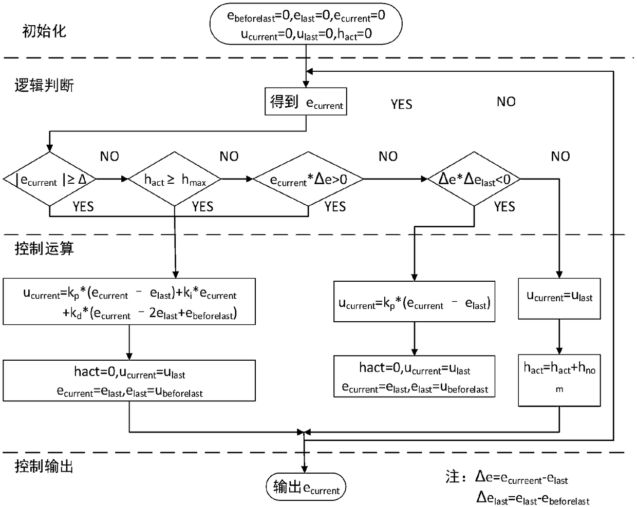
[0106] Such as image 3 As shown, Embodiment 3 of the present invention provides a train speed curve tracking control method based on time-triggered PID control, the method comprising the following steps:

[0107] Step 1: According to the force situation and Newton's second law during the train movement, a time-based single-particle model of the train can be established:

[0108]

[0109] Among them, m is the mass of the train, p(t) and v(t) are the real-time position and speed of the train, u is the traction or braking force of the train, F 0 is the basic resistance of the train, F a is the additional resistance of the train, F s is the additional resistance of the ramp, F c is the additional resistance of the curve, F t is the additional resistance of the tunnel.

[0110] The basic train resistance includes frictional resistance and air resistance. Due to the different types and structures of locomotives and vehicles, and the different operating conditions of locomo...


PUM


Abstract

The invention discloses a train velocity curve tracking control method and system based on event triggering PID control and belongs to the field of city rail train operation control technologies. Themethod comprises the steps that a single-particle motion simulation model with basic resistance being zero when a train is started is established; the actual motion state of the train is collected, and a motion state difference is acquired according to an expected motion state at a corresponding sampling time point in the single-particle motion simulation model; whether the motion state differencemeets a control update triggering condition or not is judged; and if yes, whether control state update is triggered or not is judged according to an absolute value of the motion state difference andthe change rate of the motion state difference. Through the control method and system, the number of times of calculation and burden on a controller are lowered, the fault rate is lowered, and prolonging of the service life of hardware is benefited; and it is guaranteed that the minimum interval between two update moments of a train-mounted control system has a lower bound, and the ZENO phenomenoncannot occur.

Description

technical field [0001] The invention relates to the technical field of urban rail train operation control, in particular to a train speed curve tracking control method and system based on time-triggered PID control. Background technique [0002] The control algorithm of the urban rail train automatic driving (ATO) system is the core of the train automatic driving technology. However, most of the urban rail trains use the PID (Proportion-Integration-Differentiation) speed control method during the operation process. , the operating environment is constantly changing and there are certain disturbances. The use of PID control will cause some unnecessary shocks in the train curve tracking, and the train controller will switch frequently, thereby reducing the passenger comfort, energy consumption and controller lifespan. [0003] Event-triggered control is a control theory that distinguishes time-triggered control. The calculation of system control signals and the transmission o...

Claims


Application Information

Patent Timeline
Patent Type & Authority Applications(China)
IPC IPC(8): G05D13/62G05B11/42G05B13/04
CPCG05B11/42G05B13/042G05D13/62
Inventor 高士根董海荣傅培超宁滨
Owner BEIJING JIAOTONG UNIV
Why Eureka
Try Eureka