Boot-up control method of card insertion device and circuit thereof, POS machine

A start-up control and POS machine technology, applied to computer parts, instruments, induction record carriers, etc., to achieve the effects of easy sanitation and maintenance, broad application prospects, and simplified equipment structure

Inactive Publication Date: 2018-12-21
FUJIAN LANDI COMML EQUIP CO LTD
View PDF8 Cites 2 Cited by
  • Summary
  • Abstract
  • Description
  • Claims
  • Application Information

AI Technical Summary

Problems solved by technology

Traditional POS machines usually use physical buttons to start up. Before use, they need to be turned on manually. In terms of structural design, the position of the buttons nee

Method used


Image

  • Boot-up control method of card insertion device and circuit thereof, POS machine
  • Boot-up control method of card insertion device and circuit thereof, POS machine
  • Boot-up control method of card insertion device and circuit thereof, POS machine

Examples


Embodiment 1

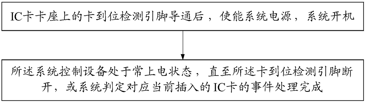
[0084] Please refer to figure 1 and figure 2 , the present embodiment provides a boot control method of a card-inserting device, the card-inserting device is suitable for an IC card, and the method of this embodiment includes:

[0085] When the card presence detection pin on the IC card holder is turned on, the system power is enabled and the system is turned on. That is to say, when the card presence detection PIN on the IC card holder is inserted into the IC card, the card presence detection pin will be turned on and connected to GND or VCC (determined according to the card detection mechanism). In short, even if the device is not In the power-on state, through the card detection mechanism of the device, it can also detect the insertion of an IC card. Therefore, this embodiment uses this mechanism to enable the power supply of the system by setting the corresponding logic circuit, so as to realize the function of starting the system just after the system is started, that ...

Embodiment 2

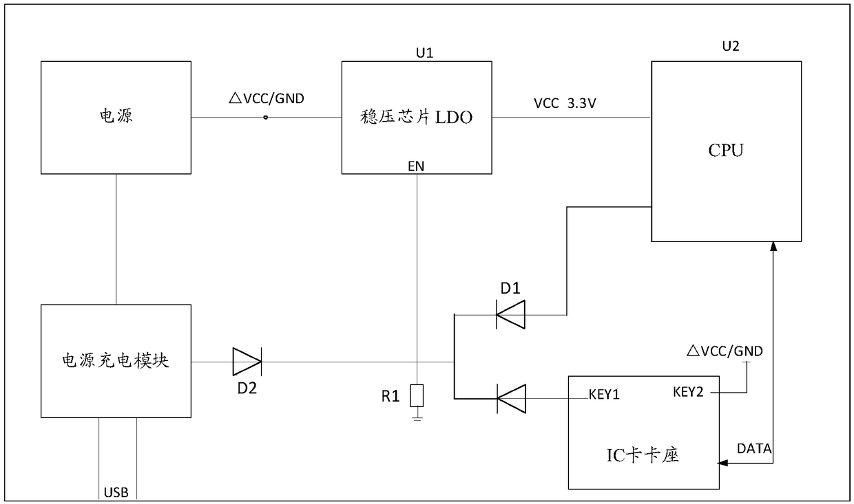
[0091] Please refer to figure 2 , the present embodiment corresponds to Embodiment 1, providing a boot control circuit of the card insertion device implementing the above method, including the card arrival detection pin in the IC card holder, the voltage stabilizing chip LDO, CPU and power supply; also includes the first A logic control device and a second logic control device.

[0092] Specifically, the power supply may be a battery, such as a lithium battery, or other common power supply modules, and the power supply is used to provide working power for the card insertion device.

[0093] Specifically, the card in-position detection pin is respectively connected to the voltage stabilizing chip LDO and the CPU through the first logic control device; the CPU, the voltage stabilizing chip LDO and the power supply are connected in sequence; the CPU is connected through the The second logic control device is connected to the voltage regulator chip LDO; the output terminal of th...

Embodiment 3

[0110] This embodiment corresponds to Embodiment 1 and Embodiment 2, and provides a POS machine, including the power-on control circuit of the card insertion device described in Embodiment 2, an IC card holder, and other peripherals. The following takes the simple version of the POS machine as an example to illustrate one of the specific application scenarios for the IC card to be turned on:

[0111] Through the IC card in-position detection, the card in-position pin will be connected to the high level VCC (or low level GND), and this signal is connected to the logic management chip pin of the system power module. The logic chip detects the card through the internal logic control. The high level (or low level) of this pin will generate a logic level output, enable the system LDO, supply power to the system, and start up.

[0112] When the user completes the transaction, one way is that the user directly pulls out the card to realize automatic shutdown; the other way is that if...


PUM


Abstract

The invention provides a startup control method of a card insertion device and a circuit thereof. The POS machine comprises a card position detecting pin in an IC card holder, a voltage stabilizing chip LDO, a CPU and a power supply. The card bit detection pin is respectively connected with the voltage regulator chip LDO and the CPU through a first logic control device; CPU, voltage stabilize chipLDO and power supply are connected in turn; The first logic control device is used for controlling conduction after the card bit detection pin is electrically connected with an IC card; The voltage stabilizing chip LDO is used for enabling the power supply and booting the system; The CPU is configured to control the regulator chip LDO to be in a normally powered state until the first logic control device is turned off after the system is powered on. The utility model not only reduces the material cost, but also improves the convenience of the shutdown and on-off machine, which is more in linewith the needs of the development of the micro-miniature equipment.

Description

technical field [0001] The invention relates to the field of switch machine control, in particular to a start-up control method of a card-inserting device, a circuit thereof, and a POS machine. Background technique [0002] For the card-inserting device in the prior art that can only be turned on and off by a specific switch button, the setting of the switch button brings material cost, and is also not conducive to miniaturization of the structure and extremely simplified design. Therefore, it is necessary to provide a power-on / off control method and a circuit thereof suitable for a card insertion device that can well solve the above-mentioned problems. [0003] In particular, with the continuous development and emergence of mobile payment, the demand for POS machines is also rising. Traditional POS machines usually use physical buttons to start up. Before use, they need to be turned on manually. In terms of structural design, the position of the buttons needs to be designe...

Claims


Application Information

Patent Timeline
IPC IPC(8): G06K7/00G07G1/14
CPCG06K7/0013G07G1/14
Inventor 刘宗铭江健琦
Owner FUJIAN LANDI COMML EQUIP CO LTD
Why Eureka
Try Eureka