Transistor and manufacturing method thereof

A manufacturing method and transistor technology, applied in semiconductor/solid-state device manufacturing, semiconductor devices, electrical components, etc., can solve problems such as loss of control, difficulty in optimizing device EAS capabilities, and inability to have a deep body region that is too thick or too deep, so as to improve work performance, improving EAS capability, and reducing body resistance

Inactive Publication Date: 2018-12-21
深圳市福来过科技有限公司
View PDF4 Cites 0 Cited by
  • Summary
  • Abstract
  • Description
  • Claims
  • Application Information

AI Technical Summary

Problems solved by technology

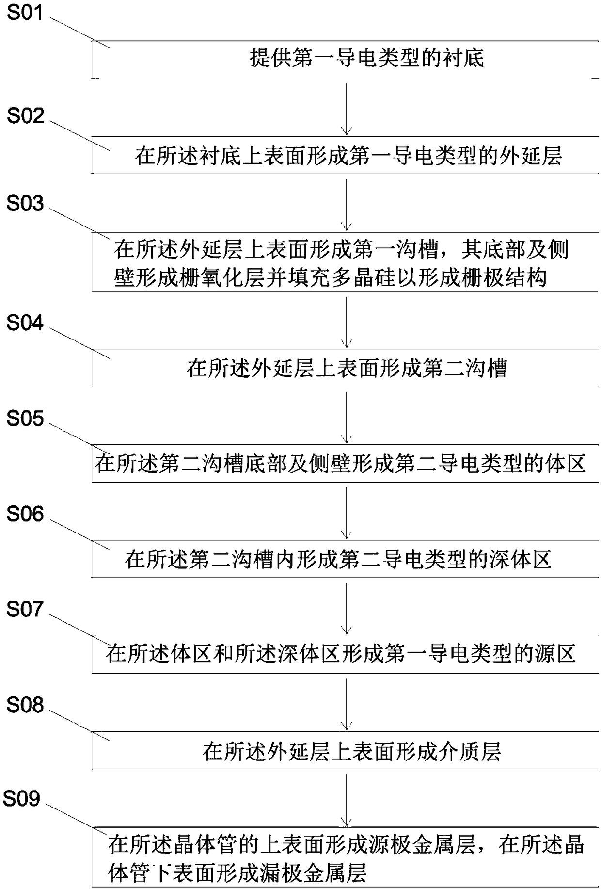
The conduction damage of the parasitic triode means that there is a parasitic triode (epitaxial layer-body region-source region) in the device itself. When the device is turned off, when the reverse current between the source and drain flows through the body region, a voltage drop occurs. If this If the voltage drop is greater than the turn-on voltage of the parasitic triode, the reverse current will turn on the parasitic triode due to the amplification of the triode, resulting in loss of control. At this time, the gate voltage can no longer turn off the VDMOS. In principle, in order to prevent failure , the key is to prevent the conduction of the parasitic triode. In order to prevent the conduction of the parasitic triode, it is necessary to reduce the resistance of the body region or increase the short-circuit area between the source region and the body region. In the current manufacturing method, due to the deep body region distance from the trench The channel area is relatively close. Considering the problem of device turn-on voltage, the deep body area cannot be made too thick or too deep, which brings great difficulties to optimize the EAS capability of the device.

Method used


Image

  • Transistor and manufacturing method thereof
  • Transistor and manufacturing method thereof
  • Transistor and manufacturing method thereof

Examples


Embodiment Construction

[0030] In order to make the objectives, technical solutions and beneficial technical effects of the present invention clearer, the technical solutions in the embodiments of the present invention will be clearly and completely described below in conjunction with the drawings in the embodiments of the present invention. Obviously, the described implementation Examples are only some embodiments of the present invention, not all embodiments. Based on the embodiments of the present invention, all other embodiments obtained by persons of ordinary skill in the art without making creative efforts belong to the protection scope of the present invention.

[0031] In the description of the present invention, it should be noted that the terms "center", "upper", "lower", "left", "right", "vertical", "horizontal", "inner", "outer" etc. The indicated orientation or positional relationship is based on the orientation or positional relationship shown in the drawings, or the orientation or posi...


PUM


Abstract

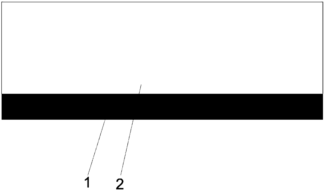
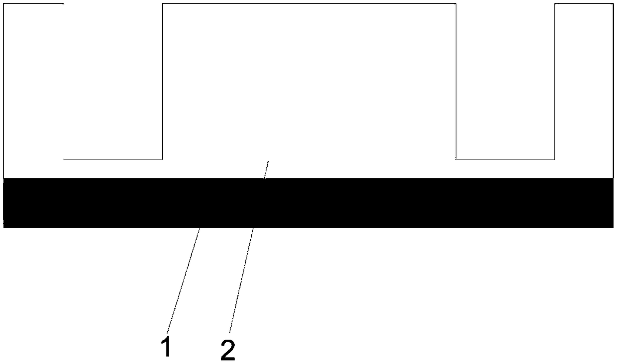
The invention provides a transistor and a manufacturing method thereof. The method comprises the following steps of: providing a substrate and an epitaxial layer; Forming a first trench on an upper surface of the epitaxial layer, forming a gate oxide layer on a bottom and a side wall thereof and filling polysilicon to form a gate structure; Forming a second trench on an upper surface of the epitaxial layer; Forming a body region of a second conductivity type at the bottom and sidewalls of the second trench; Forming a deep body region of a second conductivity type within the second trench; Forming a source region of a first conductivity type in the body region and the deep body region; Forming a dielectric layer on the upper surface of the epitaxial layer; forming A source metal layer on anupper surface of the transistor, and forming a drain metal layer on a lower surface of the transistor. Starting from optimizing the fabrication flow of the power device and changing the structure ofthe power device, the invention forms an accurate second trench and a deep body region formed by the second trench, so that the turn-on voltage of the device is more stable, the body region resistanceis reduced, and the EAS capability of the device is improved.

Description

technical field [0001] The invention relates to the technical field of semiconductors, in particular to a novel semiconductor transistor and a manufacturing method thereof. Background technique [0002] In power application equipment, VDMOS (Vertical Diffused Metal Oxide Semiconductor, Vertical Double Diffused Metal Oxide Semiconductor Field Effect Transistor) is a metal oxide semiconductor field effect transistor power device that can be widely used, which has high input impedance and high switching speed. A series of unique features such as high speed, high operating frequency, voltage control, and good thermal stability are used in switching regulated power supplies, high-frequency heating, computer interface circuits, and power amplifiers. VDMOS devices have a very important parameter, EAS (Energy Avalanche Stress, single-pulse avalanche energy), which is defined as the maximum energy that the device can consume in a single avalanche state. When a power device is workin...

Claims


Application Information

Patent Timeline
Patent Type & Authority Applications(China)
IPC IPC(8): H01L29/06H01L21/336H01L29/78
CPCH01L29/0684H01L29/66712H01L29/7802
Inventor 不公告发明人
Owner 深圳市福来过科技有限公司
Why Eureka
Try Eureka