

Wireless charger
A wireless charger and wireless charging technology, which is applied in current collectors, electric vehicles, electrical components, etc., can solve the problem of heating of wireless chargers, achieve the effects of easy handling, increase market competitiveness, and avoid serious heating
- Summary
- Abstract
- Description
- Claims
- Application Information
AI Technical Summary
Problems solved by technology
Method used
Image

Examples
Embodiment 1
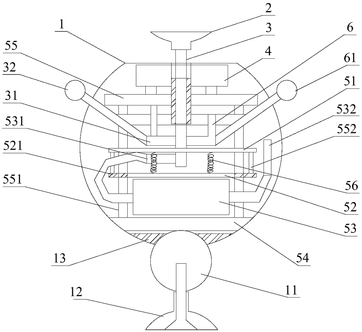
[0023] figure 1 It shows a schematic structural diagram of the wireless charger provided by the first embodiment of the present invention, the wireless charger includes a negative pressure generator, a wireless charging module 4 arranged above the negative pressure generator, and a suction cup arranged above the wireless charging module 4 2, and the hollow shaft 3; one end of the hollow shaft 3 passes through the wireless charging module 4 and communicates with the suction cup 2, and the other end of the hollow shaft 3 communicates with the negative pressure generator, which can generate negative pressure to make the suction cup 2 adsorb the adsorbed object. Wherein, the wireless charging module 4 can be realized by using existing technology, for example, the wireless charging module 4 can include a magnetic coupling coil, and realize wireless charging by using electromagnetic coupling, which is not limited in the present invention.
[0024] The wireless charger provided by t...
Embodiment 2
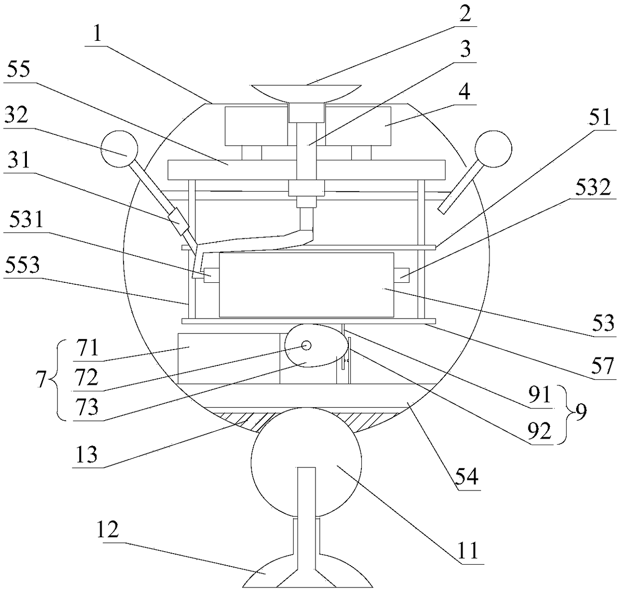
[0048] figure 2 It shows a schematic diagram of the wireless charger provided by the second embodiment of the present invention, the wireless charger includes a negative pressure generator, a wireless charging module 4 arranged above the negative pressure generator, and a suction cup 2 arranged above the wireless charging module 4 , and the hollow shaft 3; one end of the hollow shaft 3 passes through the wireless charging module 4 and communicates with the suction cup 2, and the other end of the hollow shaft 3 communicates with the negative pressure generator, which can generate negative pressure to make the suction cup 2 adsorbed Absorb objects. Wherein, the wireless charging module 4 can be realized by using existing technology, for example, the wireless charging module 4 can include a magnetic coupling coil, and realize wireless charging by using electromagnetic coupling, which is not limited in the present invention.
[0049] The wireless charger provided by the second e...
Embodiment 3
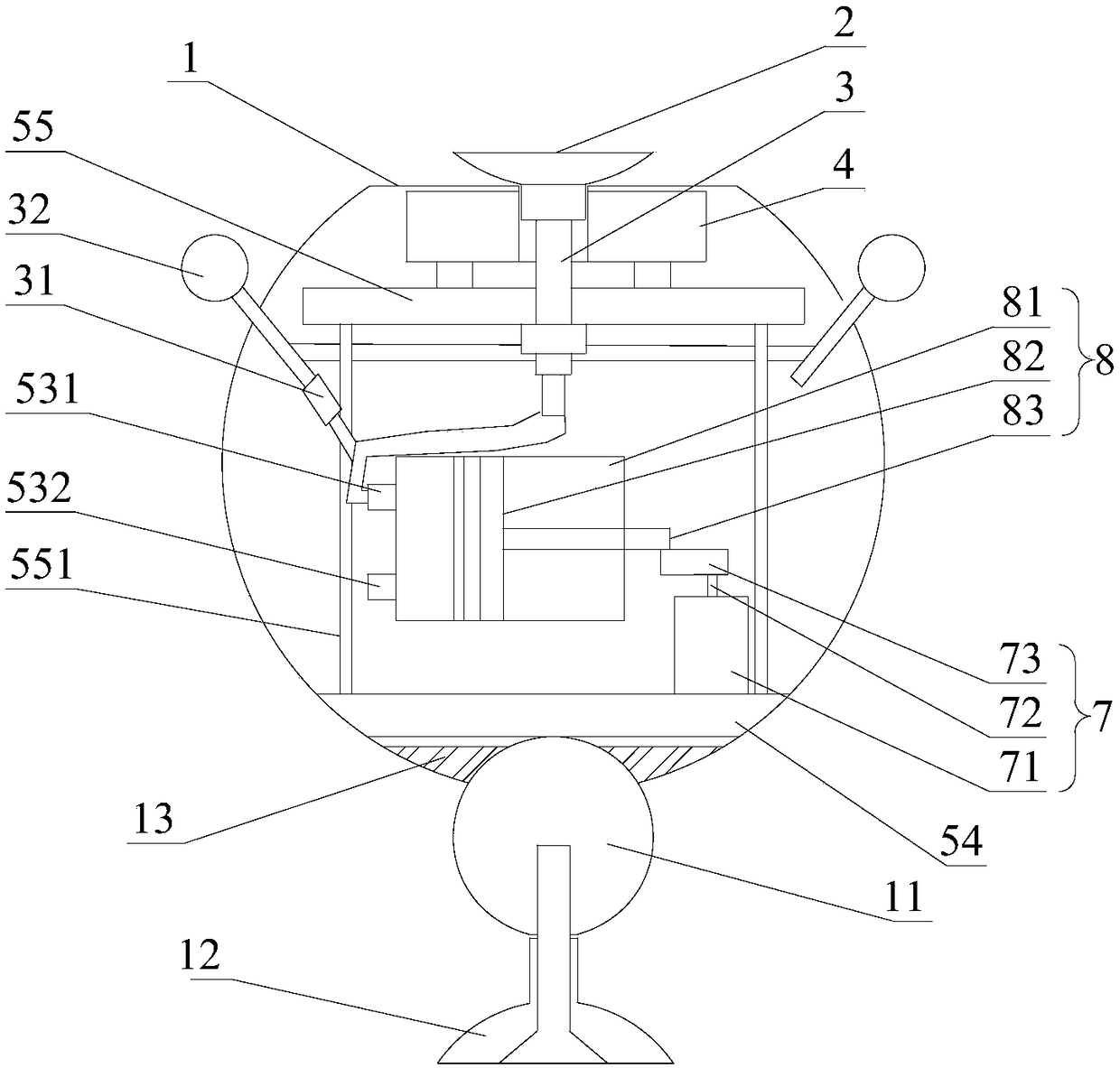
[0070] image 3 It shows a schematic structural diagram of the wireless charger provided by the third embodiment of the present invention, the wireless charger includes a negative pressure generator, a wireless charging module 4 arranged above the negative pressure generator, and a suction cup arranged above the wireless charging module 4 2, and the hollow shaft 3; one end of the hollow shaft 3 passes through the wireless charging module 4 and communicates with the suction cup 2, and the other end of the hollow shaft 3 communicates with the negative pressure generator, which can generate negative pressure to make the suction cup 2 adsorb the adsorbed object. Wherein, the wireless charging module 4 can be realized by using existing technology, for example, the wireless charging module 4 can include a magnetic coupling coil, and realize wireless charging by using electromagnetic coupling, which is not limited in the present invention.
[0071] The wireless charger provided by t...
PUM
 Abstract
Description
Claims
Application Information