Motor, wheel, and electric vehicle capable of displaying patterns or characters

A technology for displaying patterns and characters, applied in the direction of electric components, electrical components, electromechanical devices, etc., can solve the problems of no lighting effect, single display, no safety prompt function, etc. Effect

Pending Publication Date: 2018-12-21
ZHEJIANG AERLANG TECH CO LTD
View PDF0 Cites 1 Cited by
  • Summary
  • Abstract
  • Description
  • Claims
  • Application Information

AI Technical Summary

Problems solved by technology

[0004] (1) Pure mechanical motor, no lighting effect, night use, no safety reminder function
[0005] (2) The motor with LED (light-emitting diode) lamp beads has a luminous effect, but the effect is not ideal. The display is single and cannot be diversified. There are multiple patterns or text prompts

Method used


Image

  • Motor, wheel, and electric vehicle capable of displaying patterns or characters
  • Motor, wheel, and electric vehicle capable of displaying patterns or characters
  • Motor, wheel, and electric vehicle capable of displaying patterns or characters

Examples


Embodiment 1

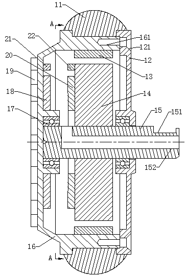
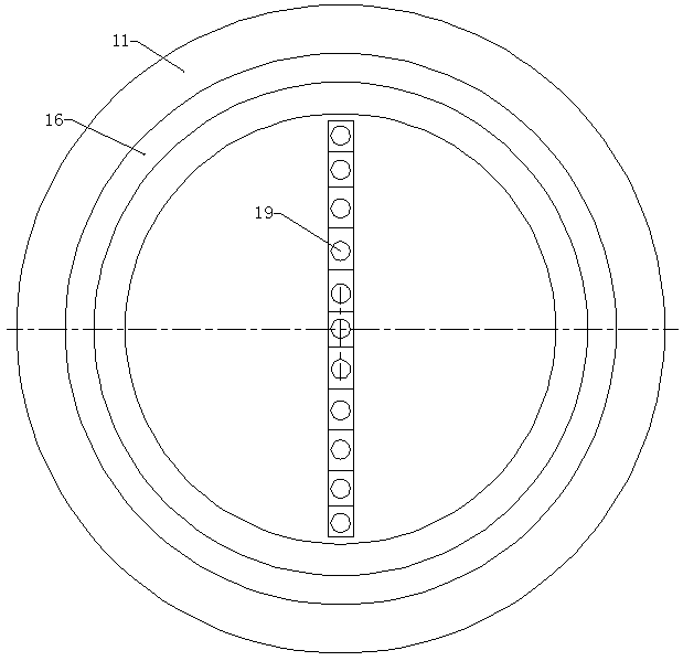
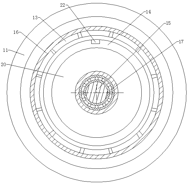
[0037] A motor that can display patterns or text, see Figure 1 to Figure 3 , including a stator 14, a front end cover 16, a rear end cover 12, a rotor magnetic steel 13, a first induction coil 18, a second induction coil 20, an LED light bar 19, a sensing unit and a wheel shaft 15, the wheel shaft 15 is a fixed shaft, and the rear The end cover 12 is installed on the rear end of the wheel shaft 15 through a bearing, the rear end of the wheel shaft 15 passes through the rear end cover 12, and the rear end cover 12 is provided with a through hole for the wheel shaft 15 to pass through at the corresponding position, that is, the wheel shaft 15 is sleeved Bearing, the outer surface of the wheel shaft 15 is interference-connected to the inner surface of the bearing inner ring, the outer surface of the bearing outer ring is sleeved with a rear end cover 12, the outer surface of the bearing outer ring is interference-connected to the rear end cover 12, and the rear end cover 12 is se...

Embodiment 2

[0053] For this example, see Figure 4 , the front end cover 16 is a transparent part, which can transmit light to the LED light beads on the LED light bar, the LED light bar 19 is glued to the inner surface of the front end cover 16, and the first induction coil 18 is glued to the circuit board of the LED light bar. On the inside surface, the receiving device 21 is also glued to the inside surface of the circuit board of the LED light bar. The height of the first induction coil is as described in Embodiment 1, which is aligned with the height of the second induction coil. Other structures and principles are as described in the embodiment 1 and will not be repeated here.

Embodiment 3

[0055] see Image 6 , in this embodiment, the front end cover 16 is a transparent part, which can transmit light to the LED light beads on the LED light bar, the LED light bar 19 is glued on the inner surface of the front end cover 16, and the first induction coil 18 is glued on the LED lamp The inner side surface of the circuit board of the strip, the front cover 16 is not directly connected to the wheel shaft 15, and the bearing between the two is canceled. This design allows the LED light bar to pass through the rotation center of the front cover 16 and extend to the edge of the front cover , to ensure that the pattern and size to be displayed are maximized, while the rear end cover 12 is installed on the wheel shaft 15 through the bearing 17, and the front end cover 16 is connected with the rear end cover 12 by fasteners. Other structures and principles are as described in Embodiment 1 and will not be repeated here.


PUM


Abstract

The invention relates to a motor capable of displaying a pattern or a character, Wheels and electric vehicles, The motor that can display patterns or text includes: including a stator, a Front cover,a rear cover, rotor magnetic steel, a first induction coil, a second induction coil, LED light bars and axles, the stator is fixedly mounted on the wheel axle, A rear end cap is rotatably mounted on the axle, A front end cover is removably and fixedly connected to the rear end cover, the rotor magnet steel is located at the circumferential periphery of the stator, the rotor magnet is fixed relative to the front end cover or the rear end cover, A LED lamp bar is arranged on the front end cover, The first induction coil is directly or indirectly mounted on the front cover, the second induction coil is mounted on the stator, the LED lamp bar comprises a circuit board and a plurality of LED lamp beads, each LED lamp bead is mounted on the circuit board, the first induction coil is connected tothe circuit board, and a micro-control unit for controlling each LED lamp bead to be on and off is mounted on the circuit board. The invention has ingenious structure and can display patterns or characters through a motor.

Description

technical field [0001] The invention relates to a motor capable of displaying patterns or characters, a wheel and an electric vehicle. Background technique [0002] At present, electric vehicles, such as balance vehicles, scooters, etc., mainly have two types of motors in the wheels, one is a purely mechanical motor, which does not have any display during the working rotation, and this type is collectively referred to as purely mechanical The motor; the second is accompanied by a light display during the working rotation, which is mainly for prompting information and lighting during riding. [0003] Although the above two methods can realize the rotary control function, they all have deficiencies. [0004] (1) Purely mechanical motor, no lighting effect, no safety reminder function for night use. [0005] (2) The motor with LED (light-emitting diode) lamp beads has a luminous effect, but the effect is not ideal. The display is single, and it cannot achieve diversification,...

Claims


Application Information

Patent Timeline
IPC IPC(8): H02K11/21H02K11/20H02J50/10
CPCH02J50/10H02K11/20H02K11/21
Inventor 臧传美
Owner ZHEJIANG AERLANG TECH CO LTD
Why Eureka
Try Eureka